Hyundai Genesis (DH): Windshield Wiper/Washer / Front Wiper Motor Repair procedures
| Removal |
| 1. |
Disconnect the negative (-) battery terminal. |
| 2. |
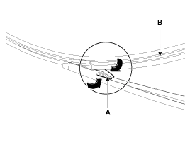
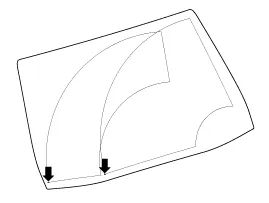
Remove the windshield wiper arm (A) and blade after removing a nut. |
| 3. |
If necessary of removing the wiper blade, push both sides of wiper tabs (A) and then remove the wiper blade.
|
| 4. |
Remove the cowl top cover.
(Refer to Body - "Cowl Top Cover") |
| 5. |
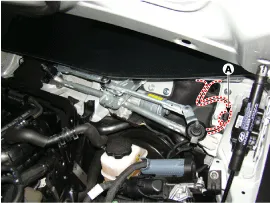
Disconnect the wiper motor connector (A) from the wiper motor & linkage assembly.
|
| 6. |
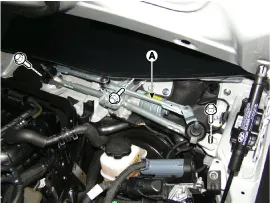
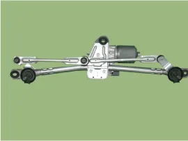
Remove the windshield wiper motor and linkage assembly (A) after removing 3 bolts.
|
| 7. |
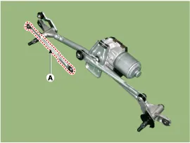
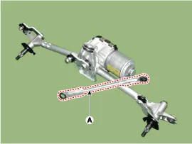
Hold the wiper motor crank arm and remove the upper linkage (A) from the wiper motor crank arm.
|

| 8. |
Remove the lower linkage (A) from the wiper motor crank arm.
|
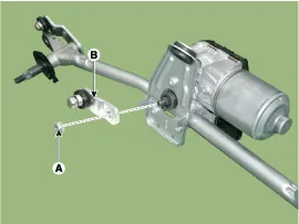
| 9. |
Remove the crank arm (B) after loosening a nut (A).
|
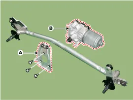
| 10. |
Remove the bracket (A) and motor (B) after loosening the screws )3EA).
|
| Installation |
| 1. |
Install the wiper motor and linkage assembly and then connect the wiper motor connector.
|
| 2. |
Install the cowl top cover. |
| 3. |
Install the windshield wiper arm and blade.
|

| 4. |
Install the wiper arm and blade to the specified position.
A: Auto stop position (Blade)
|
| Inspection |
| 1. |
The wiring harness system on the body can check the failed parts more rapidly with tester for the vehicle (GDS).
The tester (GDS) provides the following information.
|
| 2. |
Select the 'Car model' and the system to be checked in order to check the vehicle with the tester. |
| 3. |
Select the module to be checked after selecting BCM.
|
| 4. |
Select the Current data menu to search the current state of the input/output data.
The input/output data for the sensors corresponding to the 'Instrument Panel Module (IPM)' can be checked. |
Component Location 1. Cap2. Nut3. Wiper arm & blade4. Rivet5. Cowl top cover6. Bolt7. Wiper motor & linkage assembly8. Wiper motor connector
Inspection Front Washer Motor 1. With the washer motor connected to the reservoir tank, fill the reservoir tank with water. Before filling the reservoir tank with water, check the filter for foreign material or contamination.
Other information:
Hyundai Genesis (DH) 2013-2016 Service Manual: Blind Spot Detection Indicator Repair procedures
Removal Blind Spot Detection Warning Indicator 1. Disconnect the negative (-) battery terminal. 2. Remove the mirror (A). Installation Blind Spot Detection Warning Indicator 1. Install the outside mirror. 2. Connect the negative (-) battery terminal.
Hyundai Genesis (DH) 2013-2016 Service Manual: Blower Motor Repair procedures
Inspection 1. Connect the battery voltage and check the blower motor rotation. 2. If the blower motor does not operate well, replace it with a genuine blower motor check for proper operation. 3. Replace the blower motor if it is proved that there is a problem with it.
Categories
- Manuals Home
- Hyundai Genesis Owners Manual
- Hyundai Genesis Service Manual
- Body Electrical System
- Parking Assist Sensor Repair procedures
- Steering System
- New on site
- Most important about car
