Hyundai Genesis (DH): ESC(Electronic Stability Control) System / Front Wheel Speed Sensor Repair procedures
Hyundai Genesis (DH) 2013-2016 Service Manual / Brake System / ESC(Electronic Stability Control) System / Front Wheel Speed Sensor Repair procedures
| Removal |
[4WD]
| 1. |
Turn ignition switch OFF and disconnect the negative (-) battery cable. |
| 2. |
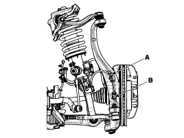
Remove the front wheel and tire (A) from the front hub.
|
| 3. |
Remove the wheel speed sensor bracket bolt (A) & wheel speed sensor mounting bolt (B).
|
| 4. |
Install in the reverse order of removal. |
[2WD]
| 1. |
Turn ignition switch OFF and disconnect the negative (-) battery cable. |
| 2. |
Remove the front wheel and tire (A) from the front hub.
|
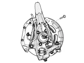
| 3. |
Remove the wheel speed sensor bracket bolt & wheel speed sensor connector (A).
|
| 4. |
Install in the reverse order of removal. |
| Inspection |
| 1. |
Turn ignition switch OFF and disconnect the negative (-) battery cable. |
| 2. |
Measure the output voltage between the terminal of the wheel speed sensor and the body ground.
|

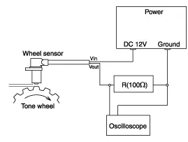
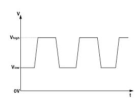
| 3. |
Compare the change of the output voltage of the wheel speed sensor to the normal change of the output voltage as shown below.
|
Components 1. Front wheel speed sensor cable2. Front wheel speed sensor
Components 1. Rear wheel speed sensor cable2. Rear wheel speed sensor
Other information:
Hyundai Genesis (DH) 2013-2016 Service Manual: Components and Components Location
C
Hyundai Genesis (DH) 2013-2016 Service Manual: Console Temperature Control Actuator Repair procedures
Inspection 1. Turn the ignition switch OFF. 2. Disconnect the console temperature control actuator connector. 3. Verify that the console temperature control actuator operates to the defrost mode when connecting 12V to terminal 3 and grounding terminal 4.
Categories
- Manuals Home
- Hyundai Genesis Owners Manual
- Hyundai Genesis Service Manual
- General Information
- 4 Wheel Drive (AWD) System
- Electric Parking Brake (EPB) Repair procedures
- New on site
- Most important about car

Copyright © 2026 www.hgenesisdh.com - 0.0304