Hyundai Genesis (DH): ESC(Electronic Stability Control) System / ESC Control Unit Repair procedures
Hyundai Genesis (DH) 2013-2016 Service Manual / Brake System / ESC(Electronic Stability Control) System / ESC Control Unit Repair procedures
| Removal |
| 1. |
Turn ignition switch OFF and disconnect the negative (-) battery cable. |
| 2. |
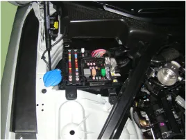
Remove the Engine room fuse & relay box (B) after removing the cover (A).
|
| 3. |
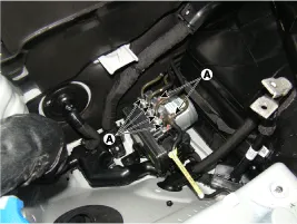
Disconnect the brake tubes (A) from the HECU by unlocking the nuts counterclockwise with a wrench.
|
| 4. |
Disconnect the ESC control unit connector. |
| 5. |
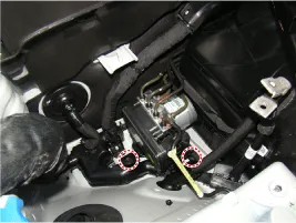
Loosen the HECU bracket bolts, then remove HECU and bracket.
|
| 6. |
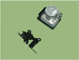
Remove the bolts, then remove the bracket from HECU.
|

| Installation |
| 1. |
Install in the reverse order of removal. |
| 2. |
Tighten the HECU mounting bolts and nuts to the specified torque. |
| 3. |
After installation, bleed the brake system.
(Refer to Brake System - "Brake System Bleeding") |
| 4. |
Connect the GDS to the data link connector located underneath the dash panel.
|
| 5. |
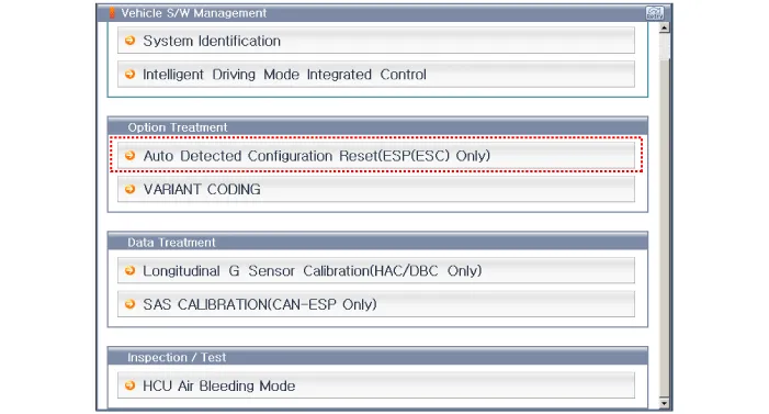
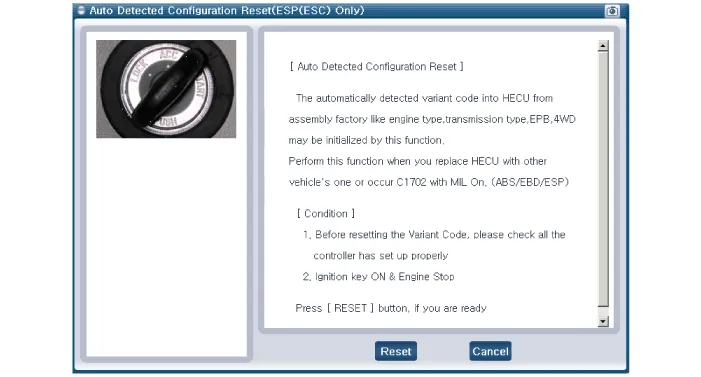
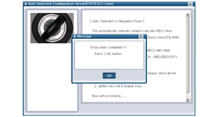
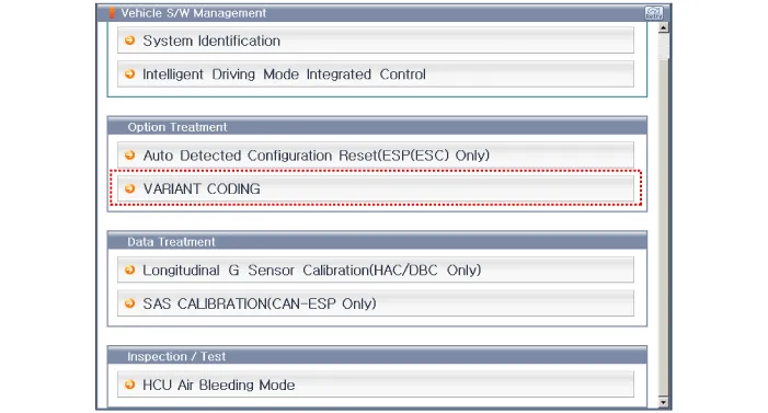
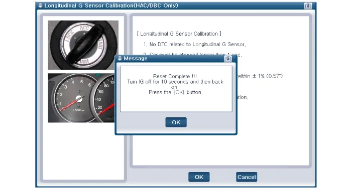
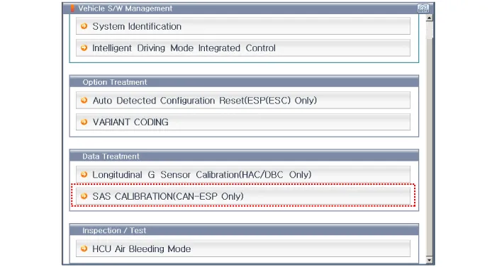
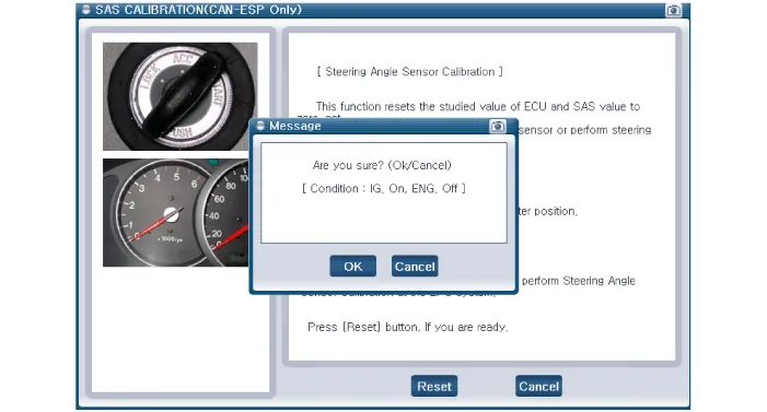
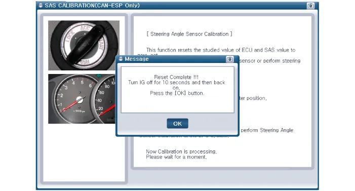
Make a selection and operate the process according to the instructions on the GDS screen.
[Auto Detected Configuration Reset]
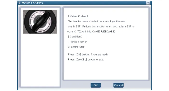
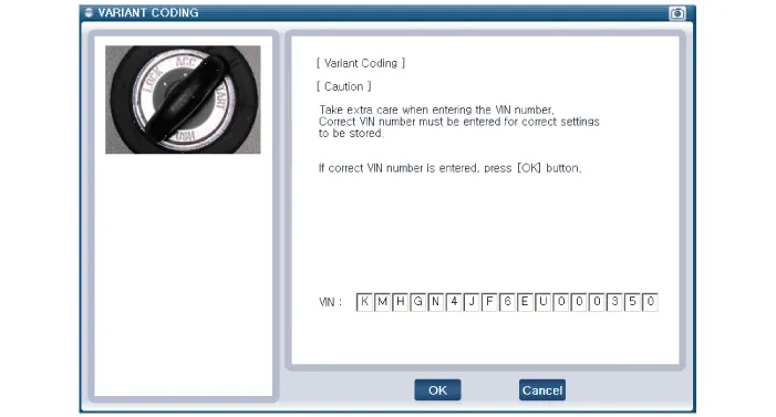
[VARIANT CODING]
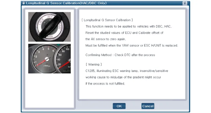
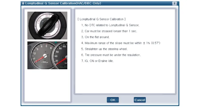
[ Longitudinal G Sensor Calibration]
[SAS CALIBRATION]
|


Operation The EBD system (Electronic Brake force Distribution) as a sub-system of the ABS system is to control the maximum braking effectiveness by the rear wheels.
Description Introduction of quick brake warning system (ESS) In case of quick brake by the driver, the brake lamp or turn signal blinks to warn against the vehicle approaching from the rear.
Other information:
Hyundai Genesis (DH) 2013-2016 Service Manual: Blind Spot Detection Indicator Components and Components Location
C
Hyundai Genesis (DH) 2013-2016 Service Manual: Blower Unit Components and Components Location
Component Location Components 1. Seal2. Intake Duct Case3. Intake Door4. Intake Actuator5. Intake Duct Case (A)6. Climate Control Air Filter7. Climate Control Air Filter Cover8. Cluster Ionizer9. Blower Upper Case10. Blower Lower Case11. Power Mosfet12.
Categories
- Manuals Home
- Hyundai Genesis Owners Manual
- Hyundai Genesis Service Manual
- Active Air Flap(AAF) Repair procedures
- Description and Operation
- Engine Mechanical System
- New on site
- Most important about car

Copyright © 2026 www.hgenesisdh.com - 0.0249