
Hyundai Genesis (DH): Cooling System / Active Air Flap(AAF) Schematic Diagrams
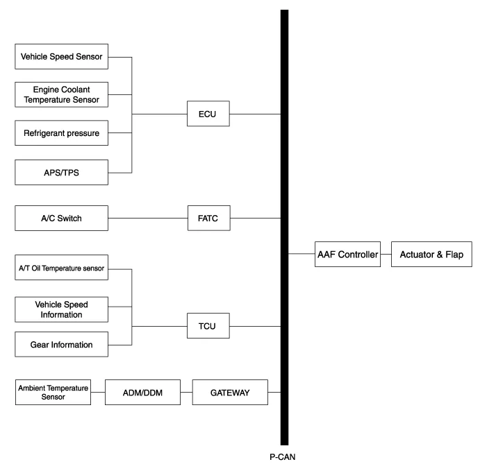
| Schematic Diagram |
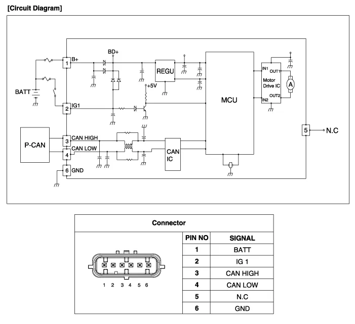
| Circuit Diagram |
Components 1. Active air housing2. Active air flap3. Active air link4. Active air actuator5. Active air duct6. Active air actuator cover
Removal and Installation 1. Disconnect the battery "-" terminal from the trunk room. 2. Remove the front bumper. (Refer to Body - "Front Bumper Cover") 3.
Other information:
Hyundai Genesis (DH) 2013-2016 Service Manual: Description and Operation
Description System Overview The System offers the following features: - Changing the state of engine ignition and power by using the start button. - Controlling external relays for ACC / IGN1 / IGN2 terminal switching and STARTER, without use of mechanical ignition switch.
Hyundai Genesis (DH) 2013-2016 Service Manual: Mode Control Actuator Repair procedures
Inspection 1. Turn the ignition switch OFF. 2. Disconnect the mode control actuator connector. 3. Verify that the mode control actuator operates to the defrost mode when connecting 12V to terminal 3 and grounding terminal 4. Verify that the mode control actuator operates to the vent mode when connected in reverse.
Categories
- Manuals Home
- Hyundai Genesis Owners Manual
- Hyundai Genesis Service Manual
- Evaporative Emission Control System
- Body Electrical System
- General Information
- New on site
- Most important about car
