Hyundai Genesis (DH): Lighting System / Head Lamps Description and Operation
Hyundai Genesis (DH) 2013-2016 Service Manual / Body Electrical System / Lighting System / Head Lamps Description and Operation
| HID Head Lamp |
| 1. |
Bulb
|
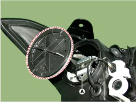
| 2. |
Ignitor
Ignitor (A) is an electromagnetic transformer that receives
current from ballast and boost voltage to turn on the arc light source
in any environment.
|
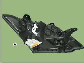
| 3. |
Ballast
|
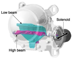
| 4. |
BI-FUNCTION
|
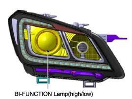
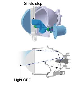
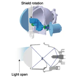
Components 1. Head lamp low beam bulb2. Head lamp high beam bulb3. Dust cap 1. HID low/high beam bulb (BI-FUNCTION)2. HID bracket3. Dust cap4.
Inspection 1. Check the battery voltage. (Low beam will be on when the battery voltage above 9V.) 2. Check the fuse and relay. 3. Check the ballast power supply terminals (if the terminals are reversed, the low beam does not illuminate.
Other information:
Hyundai Genesis (DH) 2013-2016 Service Manual: Blind Spot Detection Unit Repair procedures
Removal 1. Disconnect the negative (-) battery terminal. 2. Remove the rear bumper. (Refer to Body - "Rear Bumper") 3. Remove the BSD unit (A) after loosening the mounting nuts. Take care not to separate the bracket from rear bumper when removing the BSD sensor.
Hyundai Genesis (DH) 2013-2016 Service Manual: CO2 Sensor Repair procedures
R
Categories
- Manuals Home
- Hyundai Genesis Owners Manual
- Hyundai Genesis Service Manual
- 4 Wheel Drive (AWD) System
- Starter Repair procedures
- Steering System
- New on site
- Most important about car

Copyright © 2026 www.hgenesisdh.com - 0.0233