Hyundai Genesis (DH): Lighting System / Head Lamps Repair procedures
| Inspection |
| 1. |
Check the battery voltage. (Low beam will be on when the battery voltage above 9V.) |
| 2. |
Check the fuse and relay. |
| 3. |
Check the ballast power supply terminals (if the terminals are reversed, the low beam does not illuminate.). |
| 4. |
Check the bulb connector securely. |
| 5. |
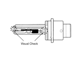
Visual check of the bulb (no filament) : damaged glass, damaged for upper parts and lower parts of glass tube. |
| 6. |
After (1)~(5), replace the ballast and the ignitor. (ballast assembly).
|
| 1. |
Durable for vibration as there is no filament. |
| 2. |
HID lamp has a longer life life than halogen lamp. |
| 3. |
Does not operate if polarity is changed. |
| 4. |
Operating input voltage : 9-16V |
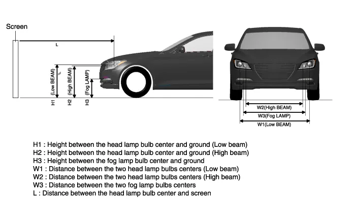
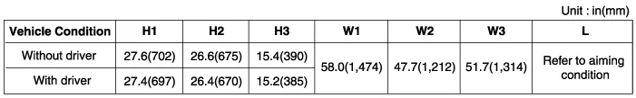
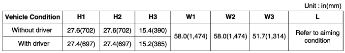
| Head Lamp Aiming Instructions |
If there are any regulations pertinent to the aiming of head
lamps in the area where the vehicle is to be used, adjust so as to meet
those requirements. |

| 1. |
Inflate the tires to the specified pressure and remove any
loads from the vehicle except the driver, spare tire, tools, coolant and
fuel. |
| 2. |
The vehicle should be placed on a flat ground. |
| 3. |
Draw vertical lines (Vertical lines passing through
respective head lamp centers) and a horizontal line (Horizontal line
passing through center of head lamps) on the screen. |
| 4. |
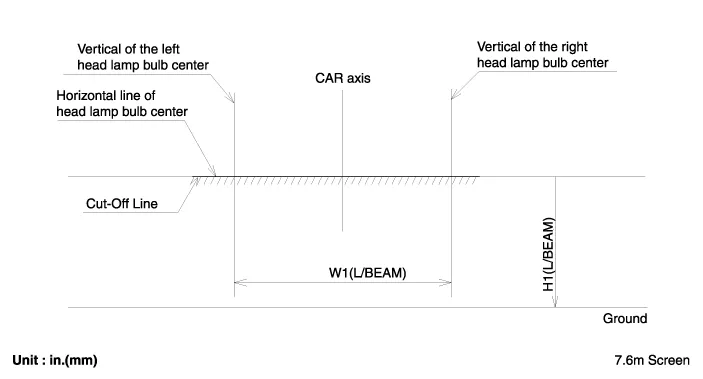
With the head lamp and battery in normal condition, aim the
head lamps so the brightest portion falls on the horizontal and vertical
lines.
Make horizontal (High_A), Vertical (Low/High_B) adjustments to the lower beam using the adjusting wheel.
|
| (Halogen type) |
| (BI-Function type) |
| (HID type) |
| 1. |
Head Lamp (Low beam)
|
| 2. |
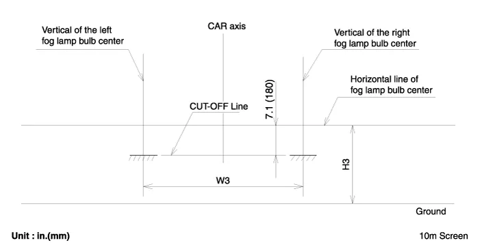
With the front fog lamp turned on, adjust the cut-off line to be located as shown in the picture below.
|
| Removal |
| 1. |
Disconnect the negative (-) battery terminal. |
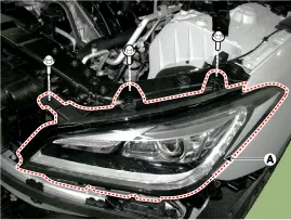
| 2. |
Remove the front bumper cover.
(Refer to Body - "Front Bumper Cover") |
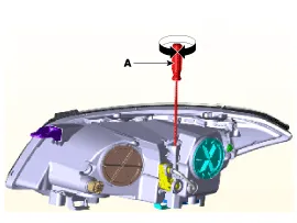
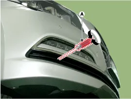
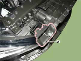
| 3. |
Loosen the head lamp (A) mounting bolt (3EA).
|
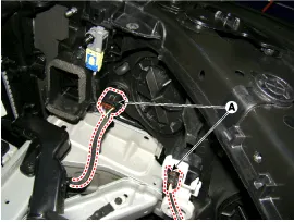
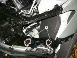
| 4. |
Disconnect the head lamp connector (A) after removing the head lamp assembly.
|
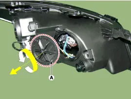
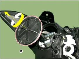
| 5. |
Remove the bulb caps from the head lamp assembly after turning in the counter clock-wise direction.
A : Head Lamp (High) Cap
B : Head Lamp (Low) Cap
|