Hyundai Genesis (DH): Front Suspension System / Front Lower Arm Repair procedures
Hyundai Genesis (DH) 2013-2016 Service Manual / Suspension System / Front Suspension System / Front Lower Arm Repair procedures
| Replacement |
| [4WD] |
Remove the lateral arm
| 1. |
Loosen the wheel nuts slightly. Raise the vehicle, and make sure it is securely supported. |
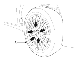
| 2. |
Remove the front wheel and tire (A) from the front hub.
|

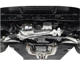
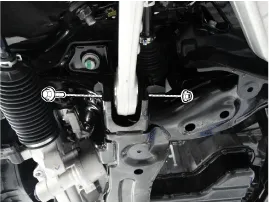
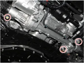
| 3. |
Loosen the steering gear box mounting bolts and then pull the steering gear box in direction of down.
|
| 4. |
Loosen the flange bolt & lock nut.
[RH]
[LH]
|
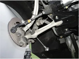
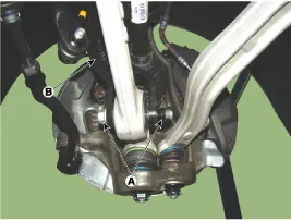
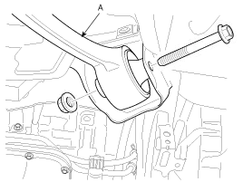
| 5. |
Unscrew the flange bolt and lock nut (A) to disconnect the lateral arm from the strut assembly (B).
|
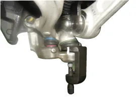
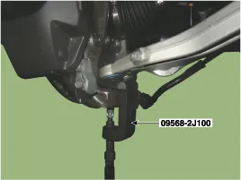
| 6. |
Remove the split pin and nut. And then disconnect the lateral arm from the knuckle using SST (09568-2J100).
|
| 7. |
Install in the reverse order of removal. |
| 8. |
Check the front alignment.
(Refer to Tires/Wheels - "Alignment") |
Remove the compression arm
| 1. |
Loosen the wheel nuts slightly. Raise the vehicle, and make sure it is securely supported |
| 2. |
Remove the front wheel and tire (A) from the front hub.
|
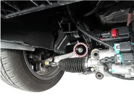
| 3. |
Loosen the nut and then remove the compression arm from knuckle.
|
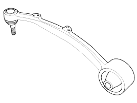
| 4. |
Loosen the flange bolt & lock nut, remove the compression arm (A).
|
| 5. |
Install in the reverse order of removal. |
| 6. |
Check the alignment.
(Refer to Tires/Wheels - "Alignment")
|
| [2WD] |
Remove the lateral arm
| 1. |
Loosen the wheel nuts slightly. Raise the vehicle, and make sure it is securely supported. |
| 2. |
Remove the front wheel and tire (A) from the front hub.
|
| 3. |
Loosen the steering gear box mounting bolts and then pull the steering gear box in direction of down.
|
| 4. |
Loosen the flange bolt & lock nut.
[RH]
[LH]
|
| 5. |
Unscrew the flange bolt and lock nut to disconnect the lateral arm from the strut assembly.
|