Hyundai Genesis (DH): Engine Control System / Engine Control Module (ECM) Schematic Diagrams
| ECM Terminal and Input/Output signal |
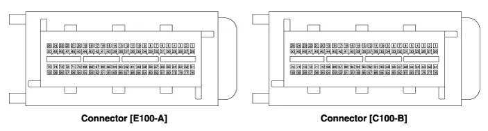
| ECM Terminal Function |
| Pin No. | Description | Connected to |
| 1 | - | ? |
| 2 | - | ? |
| 3 | - | ? |
| 4 | - | |
| 5 | Power ground | Chassis Ground |
| 6 | Power ground | Chassis Ground |
| 7 | - | ? |
| 8 | - | ? |
| 9 | 2nd CAN [High] | Multi-Purpose Check Connector |
| 10 | CAN [High] | Other control module, Data Link Connector (DLC), Multi-Purpose Check Connector |
| 11 | Fuel Tank Pressure Sensor (FTPS) signal input | Fuel Tank Pressure Sensor (FTPS) |
| 12 | - | |
| 13 | Oil pressure switch signal input | Oil Pressure Sensor (OPS) |
| 14 | Sensor power (+5V) | Accelerator Position Sensor (APS) 1 |
| 15 | Sensor power (+5V) | A/C Pressure Transducer (APT) |
| Oil Pressure Sensor (OPS) | ||
| Rail Pressure Sensor (RPS) | ||
| 16 | - | |
| 17 | - | |
| 18 | - | ? |
| 19 | - | ? |
| 20 | - | |
| 21 | Brake Switch 2 signal input | Brake Switch |
| 22 | - | ? |
| 23 | - | ? |
| 24 | Alternator PWM signal input [FR] | Alternator |
| 25 | - | |
| 26 | - | ? |
| 27 | Battery power (B+) | Ignition Switch |
| 28 | Rail Pressure Sensor (RPS) signal input | Rail Pressure Sensor (RPS) |
| 29 | - | ? |
| 30 | Power ground | Chassis Ground |
| 31 | - | ? |
| 32 | - | ? |
| 33 | - | ? |
| 34 | 2nd CAN [Low] | Multi-Purpose Check Connector |
| 35 | CAN [Low] | Other control module, Data Link Connector (DLC), Multi-Purpose Check Connector |
| 36 | - | ? |
| 37 | Sensor ground | Rail Pressure Sensor (RPS) |
| 38 | Accelerator Position Sensor (APS) 1 signal input | Accelerator Position Sensor (APS) 1 |
| 39 | - | ? |
| 40 | - | ? |
| 41 | - | |
| 42 | - | |
| 43 | Brake lamp signal input | Brake lamp |
| 44 | - | ? |
| 45 | - | ? |
| 46 | - | ? |
| 47 | - | ? |
| 48 | - | |
| 49 | - | ? |
| 50 | - | ? |
| 51 | - | ? |
| 52 | Battery power (B+) | Battery |
| 53 | - | ? |
| 54 | - | ? |
| 55 | Power ground | Chassis Ground |
| 56 | - | ? |
| 57 | - | |
| 58 | - | ? |
| 59 | Sensor ground | Accelerator Position Sensor (APS) 2 |
| 60 | Sensor ground | Accelerator Position Sensor (APS) 1 |
| 61 | Sensor ground | Fuel Tank Pressure Sensor (FTPS) |
| Oil Pressure Sensor (OPS) | ||
| 62 | - | |
| 63 | Sensor ground | A/C Pressure Transducer (APT) |
| 64 | - | ? |
| 65 | Sensor Power (+5V) | Fuel Tank Pressure Sensor (FTPS) |
| 66 | - | |
| 67 | A/C Pressure Transducer (APT) signal input | A/C Pressure Transducer (APT) |
| 68 | Accelerator Position Sensor (APS) 2 signal input | Accelerator Position Sensor (APS) 2 |
| 69 | Power Steering Pressure Sensor (PSPS) signal input | |
| 70 | Engine speed signal output | Power Distribution Module (PDM) |
| 71 | Cooling Fan Relay [High] control output | Cooling Fan Relay [High] |
| 72 | Alternator PWM signal output (COM) | Alternator |
| 73 | - | ? |
| 74 | Immobilizer communication line | Smart Key Control Module |
| 75 | Battery power (B+) | Main Relay |
| 76 | - | ? |
| 77 | Battery power (B+) | Battery |
| 78 | - | |
| 79 | - | ? |
| 80 | Power ground | Chassis ground |
| 81 | - | ? |
| 82 | - | ? |
| 83 | - | ? |
| 84 | - | ? |
| 85 | - | ? |
| 86 | - | ? |
| 87 | LIN (Local Interconnect Network) Serial Bus Line | Battery Sensor |
| 88 | - | ? |
| 89 | - | ? |
| 90 | Sensor power (+5V) | Accelerator Position Sensor (APS) 2 |
| 91 | - | |
| 92 | - | ? |
| 93 | Starter Relay control output | Starter Relay |
| 94 | Main Relay control output | Main Relay |
| 95 | Fuel pump Relay control output | Fuel pump Relay |
| 96 | Canister Close Valve (CCV) control output | Canister Close Valve (CCV) |
| 97 | - | ? |
| 98 | Dual stage oil pump | Variable Intake Solenoid (VIS) valve 2 |
| 99 | Battery power (B+) | Main Relay |
| 100 | Battery power (B+) | Main Relay |
| Pin No. | Description | Connected to |
| 1 | - | ? |
| 2 | - | |
| 3 | - | ? |
| 4 | - | ? |
| 5 | Sensor power (+5V) | Camshaft Position Sensor (CMPS) [Bank 1/Intake] |
| Camshaft Position Sensor (CMPS) [Bank 2/Exhaust] | ||
| 6 | Sensor power (+5V) | Throttle Position Sensor (TPS) |
| 7 | - | ? |
| 8 | Crank request signal output | Power Distribution Module (PDM) |
| 9 | Barometric Pressure Sensor (BPS) signal input | Barometric Pressure Sensor (BPS) |
| 10 | CVVT Oil Temperature Sensor (OTS) signal input | CVVT Oil Temperature Sensor (OTS) |
| 11 | - | |
| 12 | Throttle Position Sensor (TPS) 1 signal input | Throttle Position Sensor (TPS) 1 |
| 13 | Manifold Absolute Pressure Sensor (MAPS) signal input | Manifold Absolute Pressure Sensor (MAPS) |
| 14 | Intake Air Temperature Sensor (IATS) signal input | Intake Air Temperature Sensor (IATS) |
| 15 | Vehicle speed signal input | VDC Control Module |
| 16 | Knock Sensor (KS) [Bank 2] [High] signal input | Knock Sensor (KS) [Bank 2] |
| 17 | Knock Sensor (KS) [Bank 1] [High] signal input | Knock Sensor (KS) [Bank 1] |
| 18 | Crankshaft Position Sensor (CKPS) [High] signal input | Crankshaft Position Sensor (CKPS) |
| 19 | - | |
| 20 | - | |
| 21 | Camshaft Position Sensor (CMPS) [Bank 2/Intake] signal input | Camshaft Position Sensor (CMPS) [Bank 2/Intake] |
| 22 | - | ? |
| 23 | - | ? |
| 24 | Ignition Coil (Cylinder #1) control output | Ignition Coil (Cylinder #1) |
| 25 | - | ? |
| 26 | - | ? |
| 27 | - | ? |
| 28 | - | ? |
| 29 | - | ? |
| 30 | - | ? |
| 31 | Sensor ground | Throttle Position Sensor (TPS) 1 |
| 32 | Sensor ground | Camshaft Position Sensor (CMPS) [Bank 1/Intake] |
| Camshaft Position Sensor (CMPS) [Bank 2/Exhaust] | ||
| 33 | Sensor ground | Heated Oxygen Sensor (HO2S) [Bank 2/Sensor 2] |
| 34 | Throttle Position Sensor (TPS) 2 signal input | Throttle Position Sensor (TPS) 2 |
| 35 | Engine Coolant Temperature Sensor (ECTS) signal input | Engine Coolant Temperature Sensor (ECTS) |
| 36 | - | ? |
| 37 | - | ? |
| 38 | Heated Oxygen Sensor (HO2S) [Bank 1/Sensor 1] signal input | Heated Oxygen Sensor (HO2S) [Bank 1/Sensor 1] |
| 39 | Sensor ground | Heated Oxygen Sensor (HO2S) [Bank 1/Sensor 1] |
| 40 | Sensor Shield | Crankshaft Position Sensor (CKPS) |
| Knock Sensor (KS) #1 [Bank 1] | ||
| Knock Sensor (KS) #2 [Bank 2] | ||
| 41 | Knock Sensor (KS) [Bank 2] [Low] signal input | Knock Sensor (KS) [Bank 2] |
| 42 | Knock Sensor (KS) [Bank 1] [Low] signal input | Knock Sensor (KS) [Bank 1] |
| 43 | Crankshaft Position Sensor (CKPS) [Low] signal input | Crankshaft Position Sensor (CKPS) |
| 44 | Sensor ground | Camshaft Position Sensor (CMPS) [Bank 1/Exhaust] |
| Camshaft Position Sensor (CMPS) [Bank 2/Intake] | ||
| 45 | - | ? |
| 46 | Camshaft Position Sensor (CMPS) [Bank 2/Exhaust] signal input | Camshaft Position Sensor (CMPS) [Bank 2/Exhaust] |
| 47 | - | ? |
| 48 | Sensor power (+5V) | Barometric Pressure Sensor (BPS) |
| Manifold Absolute Pressure Sensor (MAPS) | ||
| 49 | Ignition Coil (Cylinder #3) control output | Ignition Coil (Cylinder #3) |
| 50 | - | ? |
| 51 | - | ? |
| 52 | - | ? |
| 53 | - | ? |
| 54 | - | ? |
| 55 | - | ? |
| 56 | Sensor ground | Barometric Pressure Sensor (BPS) |
| Manifold Absolute Pressure Sensor (MAPS) | ||
| Engine Coolant Temperature Sensor (ECTS) | ||
| 57 | - | ? |
| 58 | Heated Oxygen Sensor (HO2S) [Bank 2/Sensor 2] signal input | Heated Oxygen Sensor (HO2S) [Bank 2/Sensor 2] |
| 59 | Heated Oxygen Sensor (HO2S) [Bank 1/Sensor 2] signal input | Heated Oxygen Sensor (HO2S) [Bank 1/Sensor 2] |
| 60 | Sensor ground | Heated Oxygen Sensor (HO2S) [Bank 1/Sensor 2] |
| 61 | - | ? |
| 62 | - | ? |
| 63 | Heated Oxygen Sensor (HO2S) [Bank 2/Sensor 1] signal input | Heated Oxygen Sensor (HO2S) [Bank 2/Sensor 1] |
| 64 | Sensor ground | Heated Oxygen Sensor (HO2S) [Bank 2/Sensor 1] |
| 65 | Variable Intake Solenoid (VIS) Valve 1 control output | Variable Intake Solenoid (VIS) Valve 1 |
| 66 | Purge Control Solenoid Valve (PCSV) control output | Purge Control Solenoid Valve (PCSV) |
| 67 | - | ? |
| 68 | - | ? |
| 69 | Variable Intake Solenoid (VIS) Valve 2 control output | Variable Intake Solenoid (VIS) Valve 2 |
| 70 | Camshaft Position Sensor (CMPS) [Bank 1/Exhaust] signal input | Camshaft Position Sensor (CMPS) [Bank 1/Exhaust] |
| 71 | Camshaft Position Sensor (CMPS) [Bank 1/Intake] signal input | Camshaft Position Sensor (CMPS) [Bank 1/Intake] |
| 72 | - | ? |
| 73 | Sensor Power (+5V) | Camshaft Position Sensor (CMPS) [Bank 1/Exhaust] |
| Camshaft Position Sensor (CMPS) [Bank 2/Intake] | ||
| 74 | Ignition Coil (Cylinder #5) control output | Ignition Coil (Cylinder #5) |
| 75 | - | ? |
| 76 | - | ? |
| 77 | - | ? |
| 78 | - | ? |
| 79 | - | ? |
| 80 | ETC Motor [+] control output | ETC Motor |
| 81 | ETC Motor [-] control output | ETC Motor |
| 82 | Heated Oxygen Sensor (HO2S) [Bank 1/Sensor 2] Heater control output | Heated Oxygen Sensor (HO2S) [Bank 1/Sensor 2] |
| 83 | Heated Oxygen Sensor (HO2S) [Bank 2/Sensor 2] Heater control output | Heated Oxygen Sensor (HO2S) [Bank 2/Sensor 2] |
| 84 | Fuel Pressure Control Valve (FPCV) control output | Injector Drive Box (IDB) |
| 85 | Injector (Cylinder #2) control output | Injector Drive Box (IDB) |
| 86 | Injector (Cylinder #5) control output | Injector Drive Box (IDB) |
| 87 | Injector (Cylinder #3) control output | Injector Drive Box (IDB) |
| 88 | Injector (Cylinder #6) control output | Injector Drive Box (IDB) |
| 89 | Injector (Cylinder #4) control output | Injector Drive Box (IDB) |
| 90 | Injector (Cylinder #1) control output | Injector Drive Box (IDB) |
| 91 | Heated Oxygen Sensor (HO2S ) [Bank 1/Sensor 1] Heater control output | Heated Oxygen Sensor (HO2S) [Bank 1/Sensor 1] |
| 92 | Heated Oxygen Sensor (HO2S) [Bank 2/Sensor 1] Heater control output | Heated Oxygen Sensor (HO2S) [Bank 2/Sensor 1] |
| 93 | CVVT Oil Control Valve (OCV) [Bank 2/Exhaust] control output | CVVT Oil Control Valve (OCV) [Bank 2/Exhaust] |
| 94 | CVVT Oil Control Valve (OCV) [Bank 1/Exhaust] control output | CVVT Oil Control Valve (OCV) [Bank 1/Exhaust] |
| 95 | CVVT Oil Control Valve (OCV) [Bank 2/Intake] control output | CVVT Oil Control Valve (OCV) [Bank 2/Intake] |
| 96 | CVVT Oil Control Valve (OCV) [Bank 1/Intake] control output | CVVT Oil Control Valve (OCV) [Bank 1/Intake] |
| 97 | Ignition Coil (Cylinder #2) control output | Ignition Coil (Cylinder #2) |
| 98 | Ignition Coil (Cylinder #6) control output | Ignition Coil (Cylinder #6) |
| 99 | Ignition Coil (Cylinder #4) control output | Ignition Coil (Cylinder #4) |
| 100 | - | ? |
| ECM Terminal Input/Output Signal |
| Pin No. | Description | Condition | Type | Level |
| 1 | - | ? | ? | ? |
| 2 | - | ? | ? | ? |
| 3 | - | ? | ? | ? |
| 4 | - | |||
| 5 | Power ground | Idle | DC | Max. 0.1V |
| 6 | Power ground | Idle | DC | Max. 0.1V |
| 7 | - | ? | ? | ? |
| 8 | - | ? | ? | ? |
| 9 | 2nd CAN [High] | Recessive | Pulse | 2.0 ~ 3.0V |
| Dominant | 2.75 ~ 4.5V | |||
| 10 | CAN [High] | Recessive | Pulse | 2.0 ~ 3.0V |
| Dominant | 2.75 ~ 4.5V | |||
| 11 | Fuel Tank Pressure Sensor (FTPS) signal input | Idle | Analog | 0.4 ~ 4.6V |
| 12 | - | |||
| 13 | Oil pressure switch signal input | ? | ? | ? |
| 14 | Sensor power (+5V) | IG OFF | DC | Max. 0.5V |
| IG ON | 4.9 ~ 5.1V | |||
| 15 | Sensor power (+5V) | IG OFF | DC | Max. 0.5V |
| IG ON | 4.9 ~ 5.1V | |||
| 16 | - | |||
| 17 | - | ? | ? | ? |
| 18 | - | ? | ? | ? |
| 19 | - | ? | ? | ? |
| 20 | - | |||
| 21 | Brake Switch 2 signal input | Brake OFF | DC | Battery Voltage |
| Brake ON | Max. 0.5V | |||
| 22 | - | ? | ? | ? |
| 23 | - | ? | ? | ? |
| 24 | Alternator PWM signal input [FR] | Idle | PWM | High: Battery Voltage |
| Low: Max. 2.0V | ||||
| 133 | ||||
| 5 | ||||
| 25 | - | |||
| 26 | - | ? | ? | ? |
| 27 | Battery power (B+) | IG OFF | DC | Battery Voltage |
| IG ON | Max. 1.0V | |||
| 28 | Rail Pressure Sensor (RPS) signal input | Idle | DC | 1.0 ~ 2.0V |
| 29 | - | ? | ? | ? |
| 30 | Power ground | Idle | DC | Max. 0.1V |
| 31 | - | ? | ? | ? |
| 32 | - | ? | ? | ? |
| 33 | - | ? | ? | ? |
| 34 | 2nd CAN [Low] | Recessive | Pulse | 2.0 ~ 3.0V |
| Dominant | 0.5 ~ 2.25V | |||
| 35 | CAN [Low] | Recessive | Pulse | 2.0 ~ 3.0V |
| Dominant | 0.5 ~ 2.25V | |||
| 36 | - | ? | ? | ? |
| 37 | Sensor ground | Idle | DC | Max. 50mV |
| 38 | Accelerator Position Sensor (APS) 1 signal input | C.T | Analog | 0.7 ~ 0.8V |
| W.O.T | 3.85 ~ 4.35V | |||
| 39 | - | ? | ? | ? |
| 40 | - | ? | ? | ? |
| 41 | - | |||
| 42 | - | |||
| 43 | Brake lamp signal input | Brake OFF | DC | Max. 0.5V |
| Brake ON | Battery Voltage | |||
| 44 | - | ? | ? | ? |
| 45 | - | ? | ? | ? |
| 46 | - | ? | ? | ? |
| 47 | - | ? | ? | ? |
| 48 | - | |||
| 49 | - | ? | ? | ? |
| 50 | - | ? | ? | ? |
| 51 | - | ? | ? | ? |
| 52 | Battery power (B+) | Always (Without Ignition key) | DC | Battery Voltage |
| 53 | - | ? | ? | ? |
| 54 | - | ? | ? | ? |
| 55 | Power ground | Idle | DC | Max. 0.1V |
| 56 | - | ? | ? | ? |
| 57 | - | |||
| 58 | - | ? | ? | ? |
| 59 | Sensor ground | Idle | DC | Max. 0.1V |
| 60 | Sensor ground | Idle | DC | Max. 0.1V |
| 61 | Sensor ground | Idle | DC | Max. 0.1V |
| 62 | - | |||
| 63 | Sensor ground | Idle | DC | Max. 0.1V |
| 64 | - | ? | ? | ? |
| 65 | Sensor Power (+5V) | IG OFF | DC | Max. 0.5V |
| IG ON | 4.75 ~ 5.25V | |||
| 66 | - | |||
| 67 | A/C Pressure Transducer (APT) signal input | A/C ON | Analog | 0.5 ~ 4.5V |
| 68 | Accelerator Position Sensor (APS) 2 signal input | C.T | Analog | 0.29 ~ 0.46V |
| W.O.T | 1.93 ~ 2.18V | |||
| 69 | Power Steering Pressure Sensor (PSPS) signal input | Operation | Analog | 0.3 ~ 4.53V |
| 70 | Engine speed signal output | Engine Running | Pulse | High: Battery Voltage |
| Low: Max. 1.1V | ||||
| 0 | ||||
| 47.5 | ||||
| 71 | Cooling Fan Relay [High] control output | A/C ON | Pulse | High: Battery Voltage |
| Low: Max. 1.1V | ||||
| 72 | Alternator PWM signal output (COM) | IG ON | PWM | High: Min. 4.0V |
| Low: Max. 2.0V | ||||
| Frequency = 125Hz | ||||
| 73 | - | ? | ? | ? |
| 74 | Immobilizer communication line | Transmitting | DC | High: Min. Vbatt X 80% |
| Low: Max. Vbatt X 20% | ||||
| Receiving | High: Min. Vbatt X 70% | |||
| Low: Max. Vbatt X 30% | ||||
| 75 | Battery power (B+) | IG OFF | DC | Battery Voltage |
| IG ON | Max. 1.0V | |||
| 76 | - | ? | ? | ? |
| 77 | Battery power (B+) | Always (Without Ignition key) | DC | Battery Voltage |
| 78 | - | |||
| 79 | - | ? | ? | ? |
| 80 | Power ground | Idle | DC | Max. 0.1V |
| 81 | - | ? | ? | ? |
| 82 | - | ? | ? | ? |
| 83 | - | ? | ? | ? |
| 84 | - | ? | ? | ? |
| 85 | - | ? | ? | ? |
| 86 | - | ? | ? | ? |
| 87 | LIN (Local Interconnect Network) Serial Bus Line | Transmitting | DC | High: Min. Vbatt X 80% |
| Low: Max. Vbatt X 20% | ||||
| Receiving | High: Min. Vbatt X 70% | |||
| Low: Max. Vbatt X 30% | ||||
| 88 | - | ? | ? | ? |
| 89 | - | ? | ? | ? |
| 90 | Sensor power (+5V) | IG OFF | DC | Max. 0.5V |
| IG ON | 4.75 ~ 5.25V | |||
| 91 | - | |||
| 92 | - | ? | ? | ? |
| 93 | Starter Relay control output | Relay OFF | DC | Battery Voltage |
| Relay ON | Max 1.1V | |||
| 94 | Main Relay control output | Relay OFF | DC | Battery Voltage |
| Relay ON | Max 1.7V | |||
| 95 | Fuel Pump Relay control output | Relay OFF | DC | Battery Voltage |
| Relay ON | Max 1.0V | |||
| 96 | Canister Close Valve (CCV) control output | Active | Pulse | High: Battery Voltage |
| Inactive | Low: Max. 1.0V | |||
| ? | Vpeak: Max. 70V | |||
| 97 | - | ? | ? | ? |
| 98 | Dual stage oil pump | ? | ? | ? |
| 99 | Battery power (B+) | IG OFF | DC | Battery Voltage |
| IG ON | Max. 1.0V | |||
| 100 | Battery power (B+) | IG OFF | DC | Battery Voltage |
| IG ON | Max. 1.0V |
| Pin No. | Description | Condition | Type | Level |
| 1 | - | ? | ? | ? |
| 2 | - | |||
| 3 | - | ? | ? | ? |
| 4 | - | ? | ? | ? |
| 5 | Sensor power (+5V) | IG OFF | DC | Max. 0.5V |
| IG ON | 4.75 ~ 5.25V | |||
| 6 | Sensor power (+5V) | IG OFF | DC | Max. 0.5V |
| IG ON | 4.75 ~ 5.25V | |||
| 7 | - | ? | ? | ? |
| 8 | Crank request signal output | S/W OFF | DC | Max. 1.0V |
| S/W ON | Battery Voltage | |||
| 9 | Barometric Pressure Sensor (BPS) signal input | IG ON | Analog | Approx. 4.0V |
| 10 | CVVT Oil Temperature Sensor (OTS) signal input | IG ON | Analog | 3.2V at -40 |
Components Location 1. ECM (Engine Control Module)2. Barometric Pressure Sensor (BPS)3. Intake Air Temperature Sensor (IATS)4. Manifold Absolute Pressure Sensor (MAPS)5.
Removal For the vehicle equipped with the immobilizer, the procedures shown below must be performed after replacing the ECM. [In the case of installing used ECM] 1) Perform "ECM Neutral mode" procedure with GDS.
Other information:
Hyundai Genesis (DH) 2013-2016 Service Manual: Compressor oil Repair procedures
Oil Specification 1. The HFC-134a system requires synthetic (PAG) compressor oil whereas the R-12 system requires mineral compressor oil. The two oils must never be mixed. 2. Compressor (PAG) oil varies according to compressor model. Be sure to use oil specified for the compressor model.
Hyundai Genesis (DH) 2013-2016 Service Manual: Condenser Repair procedures
Inspection 1. Check the condenser fins for clogging and damage. If they are clogged, clean them with water, and blow them with compressed air. If they are bent, gently bend them using a screwdriver or pliers. 2. Check the condenser connections for leakage, and repair or replace it, if required.
Categories
- Manuals Home
- Hyundai Genesis Owners Manual
- Hyundai Genesis Service Manual
- General Information
- 4 Wheel Drive (AWD) System
- Parking Assist Sensor Repair procedures
- New on site
- Most important about car
