Hyundai Genesis (DH): Engine Control System / Components and Components Location
| Components Location |
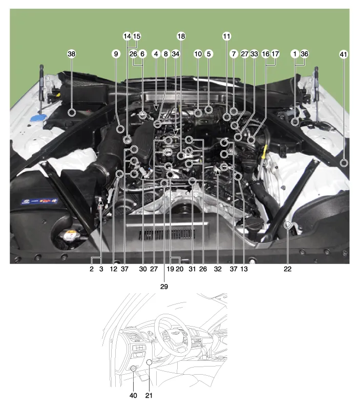
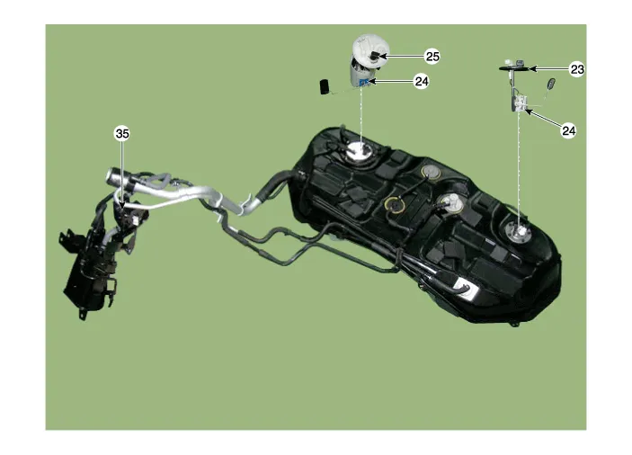
| 1. ECM (Engine Control Module) 2. Barometric Pressure Sensor (BPS) 3. Intake Air Temperature Sensor (IATS) 4. Manifold Absolute Pressure Sensor (MAPS) 5. Engine Coolant Temperature Sensor (ECTS) 6. Throttle Position Sensor (TPS) [integrated into ETC Module] 7. Crankshaft Position Sensor (CKPS) 8. Camshaft Position Sensor (CMPS) [Bank 1 / Intake] 9. Camshaft Position Sensor (CMPS) [Bank 1 / Exhaust] 10. Camshaft Position Sensor (CMPS) [Bank 2 / Intake] 11. Camshaft Position Sensor (CMPS) [Bank 2 / Exhaust] 12. Knock Sensor (KS) [Bank 1] 13. Knock Sensor (KS) [Bank 2] 14. Heated Oxygen Sensor (HO2S) [Bank 1 / Sensor 1] 15. Heated Oxygen Sensor (HO2S) [Bank 1 / Sensor 2] 16. Heated Oxygen Sensor (HO2S) [Bank 2 / Sensor 1] 17. Heated Oxygen Sensor (HO2S) [Bank 2 / Sensor 2] 18. Rail Pressure Sensor (RPS) 19. CVVT Oil Temperature Sensor (OTS) 20. CVVT Oil Pressure Sensor (OPS) 21. Accelerator Position Sensor (APS) | 22. A/C Pressure Transducer (APT) 23. Fuel Tank Pressure Sensor (FTPS) 24. Fuel Level Sensor (FLS) 25. Fuel Pressure Sensor (FPS) 26. ETC Motor (integrated info ETC module] 27. Injector 28. Purge control solenoid valve (PCSV) 29. CVVT Oil Control Valve (OCV) [Bank 1 / Intake] 30. CVVT Oil Control Valve (OCV) [Bank 1 / Exhaust] 31. CVVT Oil Control Valve (OCV) [Bank 2 / Intake] 32. CVVT Oil Control Valve (OCV) [Bank 2 / Exhaust] 33. Fuel Pressure Control Valve (FPCV) 34. Variable Intake Solenoid (VIS) valve 35. Canister Close Valve (CCV) 36. Injector Drive Box (IDB) 37. Ignition Coil 38. Main Relay 39. Fuel Pump Relay 40. Data Link Connector (DLC) [16 pin] 41. Multi-Purpose Check Connector [20 pin] |
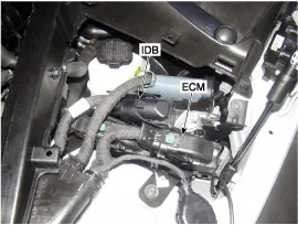
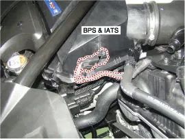
| 1. ECM (Engine Control Module) 36. Injector Drive Box (IDB) | 2. Barometric Pressure Sensor (BPS) 3. Intake Air temperature Sensor (IATS) |
|
|
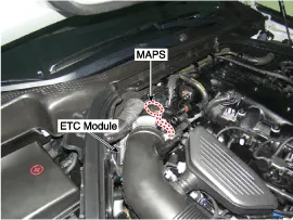
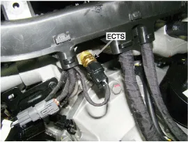
| 4. Manifold Absolute Pressure Sensor (MAPS) 6. Throttle Position Sensor (TPS) [integrated into ETC Module] 26. ETC Motor [integrated into ETC Module] | 5. Engine Coolant Temperature Sensor (ECTS) |
|
|
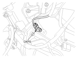
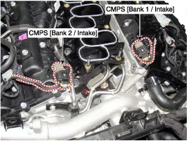
| 7. Crankshaft Position Sensor (CKPS) | 8. Camshaft Position Sensor (CMPS) [Bank 1 / Intake] 10. Camshaft Position Sensor (CMPS) [Bank 2 /Intake] |
|
|
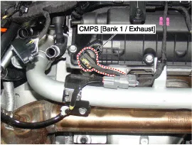
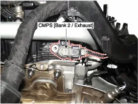
| 9. Camshaft Position Sensor (CMPS) [Bank 1 / Exhaust] | 11. Camshaft Position Sensor (CMPS) [Bank 2 / Exhaust] |
|
|
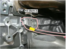
| 12. Knock Sensor (KS) [Bank 1] | 13. Knock Sensor (KS) [Bank 2] |
|
|
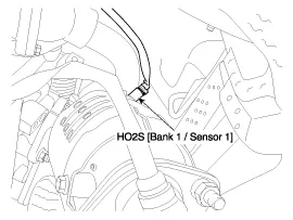
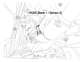
| 14. Heated Oxygen Sensor (HO2S) [Bank 1 / Sensor 1] | 15. Heated Oxygen Sensor (HO2S) [Bank 1 / Sensor 2] |
|
|
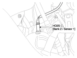
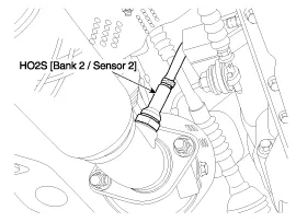
| 16. Heated Oxygen Sensor (HO2S) [Bank 2 / Sensor 1] | 17. Heated Oxygen Sensor (HO2S) [Bank 2 / Sensor 2] |
|
|
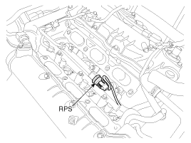
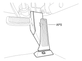
| 18. Rail Pressure Sensor (RPS) | 21. Accelerator Position Sensor (APS) |
|
|
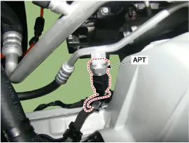
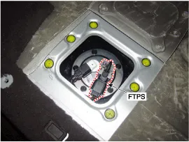
| 22. A/C Pressure Transducer (APT) | 23. Fuel Tank Pressure Sensor (FTPS) |
|
|
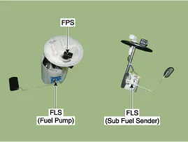
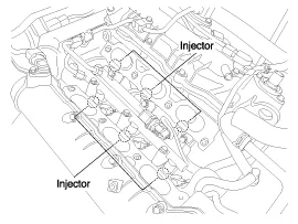
| 24. Fuel Level Sensor (FLS) 25. Fuel Pressure Sensor (FPS) | 27. Injector |
|
|
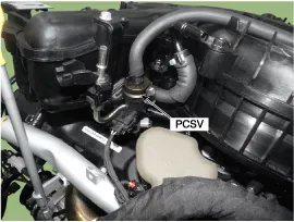
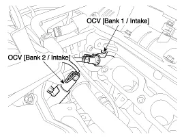
| 28. Purge Control Solenoid Valve (PCSV) | 29. CVVT Oil Control Valve (OCV) [Bank 1 / Intake] 31. CVVT Oil Control Valve (OCV) [Bank 2 / Intake] |
|
|
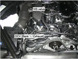
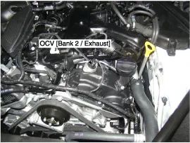
| 30. CVVT Oil Control valve (OCV) [Bank 1/ Exhaust] 34. Variable Intake Solenoid (VIS) valve | 32. CVVT Oil Control valve (OCV) [Bank 2/ Exhaust] |
|
|
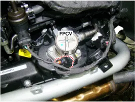
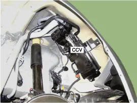
| 33. Fuel Pressure Control Valve (FPCV) | 35. Canister Close Valve (CCV) |
|
|
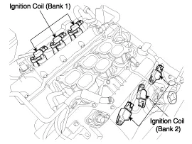
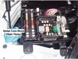
| 37. Ignition Coil | 38. Main Relay |
|
|
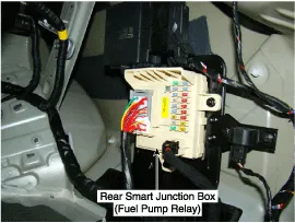
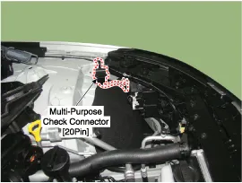
| 39. Fuel Pump Relay | 41. Multi - Purpose Check Connector [20Pin] |
|
|

OBD-II review 1. Overview The California Air Resources Board (CARB)launched the regulation of OBD (On Board Diagnostics) for vehicles sold in California starting with the 1988 model year.
ECM Terminal and Input/Output signal ECM Terminal Function Connector [E100-A] Pin No.DescriptionConnected to1-?2-?3-?4-5Power groundChassis Ground6Power groundChassis Ground7-?8-?92nd CAN [High]Multi-Purpose Check Connector10CAN [High]Other control module, Data Link Connector (DLC), Multi-Purpose Check Connector11Fuel Tank Pressure Sensor (FTPS) signal inputFuel Tank Pressure Sensor (FTPS)12-13Oil pressure switch signal inputOil Pressure Sensor (OPS)14Sensor power (+5V)Accelerator Position Sensor (APS) 115Sensor power (+5V)A/C Pressure Transducer (APT)Oil Pressure Sensor (OPS)Rail Pressure Sensor (RPS)16-17-18-?19-?20-21Brake Switch 2 signal inputBrake Switch22-?23-?24Alternator PWM signal input [FR]Alternator25-26-?27Battery power (B+)Ignition Switch28Rail Pressure Sensor (RPS) signal inputRail Pressure Sensor (RPS)29-?30Power groundChassis Ground31-?32-?33-?342nd CAN [Low]Multi-Purpose Check Connector35CAN [Low]Other control module, Data Link Connector (DLC), Multi-Purpose Check Connector36-?37Sensor groundRail Pressure Sensor (RPS)38Accelerator Position Sensor (APS) 1 signal inputAccelerator Position Sensor (APS) 139-?40-?41-42-43Brake lamp signal inputBrake lamp44-?45-?46-?47-?48-49-?50-?51-?52Battery power (B+)Battery53-?54-?55Power groundChassis Ground56-?57-58-?59Sensor groundAccelerator Position Sensor (APS) 260Sensor groundAccelerator Position Sensor (APS) 161Sensor groundFuel Tank Pressure Sensor (FTPS)Oil Pressure Sensor (OPS)62-63Sensor groundA/C Pressure Transducer (APT)64-?65Sensor Power (+5V)Fuel Tank Pressure Sensor (FTPS)66-67A/C Pressure Transducer (APT) signal inputA/C Pressure Transducer (APT)68Accelerator Position Sensor (APS) 2 signal inputAccelerator Position Sensor (APS) 269Power Steering Pressure Sensor (PSPS) signal input70Engine speed signal outputPower Distribution Module (PDM)71Cooling Fan Relay [High] control outputCooling Fan Relay [High]72Alternator PWM signal output (COM)Alternator73-?74Immobilizer communication lineSmart Key Control Module75Battery power (B+)Main Relay76-?77Battery power (B+)Battery78-79-?80Power groundChassis ground81-?82-?83-?84-?85-?86-?87LIN (Local Interconnect Network) Serial Bus LineBattery Sensor88-?89-?90Sensor power (+5V)Accelerator Position Sensor (APS) 291-92-?93Starter Relay control outputStarter Relay94Main Relay control outputMain Relay95Fuel pump Relay control outputFuel pump Relay 96Canister Close Valve (CCV) control outputCanister Close Valve (CCV)97-?98Dual stage oil pumpVariable Intake Solenoid (VIS) valve 299Battery power (B+)Main Relay100Battery power (B+)Main Relay Connector [C100-B] Pin No.
Other information:
Hyundai Genesis (DH) 2013-2016 Service Manual: General Safety Information and Caution
Instructions When Handling Refrigerant 1. R-134a liquid refrigerant is highly volatile. A drop on the skin of your hand could result in localized frostbite. When handling the refrigerant, be sure to wear gloves. 2. It is standard practice to wear goggles or glasses to protect your eyes, and gloves to protect your hands.
Hyundai Genesis (DH) 2013-2016 Service Manual: Cluster Ionizer Repair procedures
Inspection 1. Press the MODE switch more than 4 times within 2 seconds while pressing the OFF switch. DisplayFail description00Normal51Cluster ion generator fault * For diagnostic procedure, refer to DTC guide. Replacement 1. Disconnect the negative (-) battery terminal.
Categories
- Manuals Home
- Hyundai Genesis Owners Manual
- Hyundai Genesis Service Manual
- Brake System
- 4 Wheel Drive (AWD) System
- Engine Mechanical System
- New on site
- Most important about car
