Hyundai Genesis (DH): Blind Spot Detection system / Blind Spot Detection Switch Repair procedures
Hyundai Genesis (DH) 2013-2016 Service Manual / Body Electrical System / Blind Spot Detection system / Blind Spot Detection Switch Repair procedures
| Removal |
| 1. |
Disconnect the negative (-) battery terminal. |
| 2. |
Remove the crash pad lower panel.
(Refer to Body - "Crash Pad") |
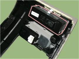
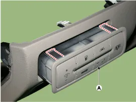
| 3. |
Remove the blind spot detection (BSD) switch (A) after disengaging the mounting clip.
|
| Installation |
| 1. |
Install the crash pad side switch assembly after connecting the connector. |
| 2. |
Install the crash pad lower panel. |
| Inspection |
| 1. |
Disconnect the BSD switch connector.
|
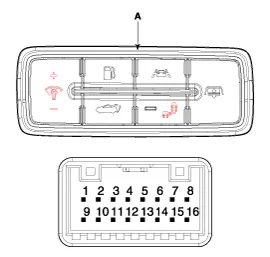
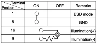
| 2. |
Operate the BSD switch, then check for continuity between terminals of BSD switch connector.
|
Circuit Diagram
Components 1. AVM Camera2. Ambient temperature sensor3. Puddle lamp
Other information:
Hyundai Genesis (DH) 2013-2016 Service Manual: Auto Head Lamp Leveling Unit Troubleshooting
Inspection with GDS Initialization and diagnosis sequence by using GDS equipment. The following is the summarized A/S procedure. NoProcedure1Park the vehicle on level ground2Tire check3IGN1 ON4Head lamp Low Beam ON5Connection with diagnostic tool6Initial command by diagnostic tool7Clear DTC Code8IGN1 OFF > ON9Re- Connection with diagnostic t
Hyundai Genesis (DH) 2013-2016 Service Manual: Description and Operation
Description System Overview The System offers the following features: - Changing the state of engine ignition and power by using the start button. - Controlling external relays for ACC / IGN1 / IGN2 terminal switching and STARTER, without use of mechanical ignition switch.
Categories
- Manuals Home
- Hyundai Genesis Owners Manual
- Hyundai Genesis Service Manual
- Active Air Flap(AAF) Repair procedures
- Restraint
- 4 Wheel Drive (AWD) System
- New on site
- Most important about car

Copyright © 2026 www.hgenesisdh.com - 0.0227