Hyundai Genesis (DH): Windshield Deicer / Windshield Deicer Switch Repair procedures
Hyundai Genesis (DH) 2013-2016 Service Manual / Body Electrical System / Windshield Deicer / Windshield Deicer Switch Repair procedures
| Inspection |
| 1. |
In the body electrical system, failure can be quickly diagnosed by using the vehicle diagnostic system (GDS).
|
| 2. |
Select the 'Car model' and the system to be checked in order to check the vehicle with the tester. |
| 3. |
Select the 'Smart Junction Block(SJB)' to check the windshield deicer. |
| 4. |
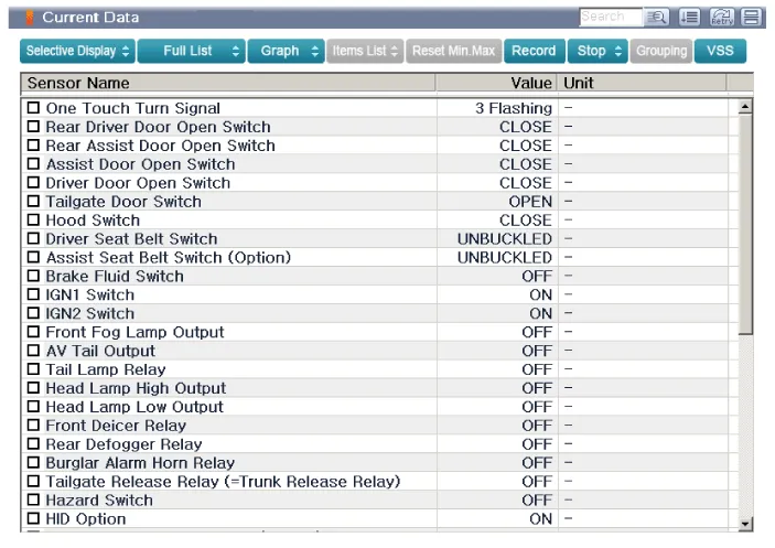
Select the "Current date" menu to search the current state of the input/output data.
The input/output data for the sensors corresponding to the 'Smart Junction Block(SJB)' can be checked.
|
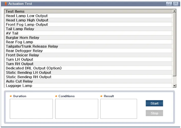
| 5. |
Select "Actuation test", if you want to check the Smart Junction Block(SJB) data operation forcefully.
|
| Removal |
| 1. |
Disconnect the negative (-) battery terminal. |
| 2. |
Remove the heater and A/C contol unit.
(Refer to Heating, Ventilation, Air conditioning - "Heater & A/C Control Unit (Dual)") |
| Installation |
| 1. |
Install the heater and A/C control unit. |
| 2. |
Connect the negative (-) battery terminal. |
Inspection 1. Remove the cowl top cover. (Refer to Body - "Cowl Top Cover") 2. Disconnect the windshield deicer connector (A) from the wiper motor linkage.
Other information:
Hyundai Genesis (DH) 2013-2016 Service Manual: Description and Operation
Description Integrated Rain Sensor Integrated rain sensor (A) controls three systems: front wiper, auto-light, and central air conditioner. 1. Wiper Control System When "AUTO" switch signal is received from the multi-function switch on the right, the integrated rain sensor detects the amount of rainfall.
Hyundai Genesis (DH) 2013-2016 Service Manual: Auto Light Sensor Components and Components Location
C
Categories
- Manuals Home
- Hyundai Genesis Owners Manual
- Hyundai Genesis Service Manual
- Suspension System
- Body Electrical System
- Description and Operation
- New on site
- Most important about car

Copyright © 2026 www.hgenesisdh.com - 0.0289