Hyundai Genesis (DH): IMS(Integrated Memory System) / Tilt & Telescope Control (SCM) Repair procedures
Hyundai Genesis (DH) 2013-2016 Service Manual / Body Electrical System / IMS(Integrated Memory System) / Tilt & Telescope Control (SCM) Repair procedures
| Inspection |
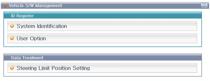
Ims Mode Setting With GDS
| 1. |
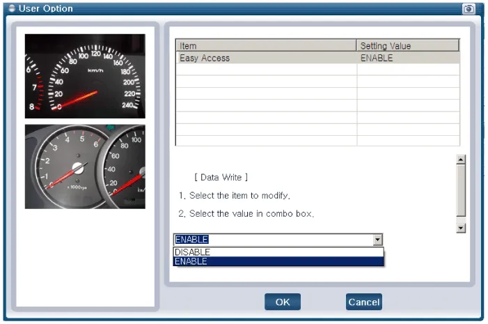
You can turn ON/OFF of IMS tilt & telescope control option with the user option program. |
| 2. |
Select model and "body control module" menu. |
| 3. |
Select the "Steering Limit Position Setting".
|
| 4. |
Select the "ENABLE".
|
Circuit Diagram NO.Function (Connector A)NO.Function (Connector B)1B+ (ECU)1Tele motor backward (tele in)2Sensor VCC2Tilt motor up3Tilt sensor3Tilt motor down4Tele sensor4Tele motor forward (tele out)5Tilt up switch5Power GND6Tele backward (tele in) 5W6-7-7Power B+8B_CAN_High8-9B_CAN_Low9-10ECU GND10-11IGN111-12Sensor GND12-13-13-14-14-15Tilt down switch15-16Tele forward (tele out) switch16-17-17-18-18-19-19-20-20-
Other information:
Hyundai Genesis (DH) 2013-2016 Service Manual: Blind Spot Detection Indicator Components and Components Location
C
Hyundai Genesis (DH) 2013-2016 Service Manual: A/C Pressure Transducer Description and Operation
Description The A/C Pressure Transducer (APT) converts the pressure value of high-pressure line into voltage value after measuring it. By converted voltage value, engine ECU controls the cooling fan by operating it at high speed or low speed.
Categories
- Manuals Home
- Hyundai Genesis Owners Manual
- Hyundai Genesis Service Manual
- Suspension System
- Transmission Control Module (TCM) Repair procedures
- Active Air Flap(AAF) Repair procedures
- New on site
- Most important about car

Copyright © 2026 www.hgenesisdh.com - 0.0255