Hyundai Genesis (DH): Intake And Exhaust System / Surge Tank Repair procedures
Hyundai Genesis (DH) 2013-2016 Service Manual / Engine Mechanical System / Intake And Exhaust System / Surge Tank Repair procedures
| Removal and Installation |
| 1. |
Disconnect the battery "-" terminal from the trunk room. |
| 2. |
Remove the engine cover. |
| 3. |
Remove the engine room cover.
(Refer to Engine And Transaxle Assembly - "Engine Cover") |
| 4. |
Remove the Cowl Top Cover.
(Refer to Body - "Cowl Top Cover") |
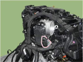
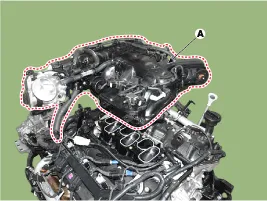
| 5. |
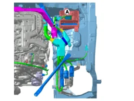
Remove the Engine room bulkhead (A).
|
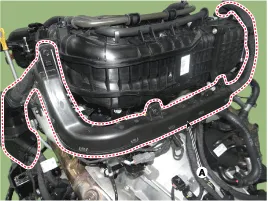
| 6. |
Remove the air cleaner assembly.
(Refer to Intake Exhaust System - "Air Cleaner") |
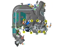
| 7. |
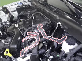
Disconnect the fuel hose (A,B) and Brake vacuum hose (C).
|
| 8. |
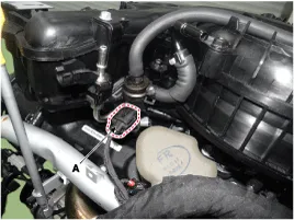
Disconnect the PCSV connector (A).
|
| 9. |
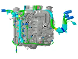
Disconnect the VIS connector (A), Condenser connector (B), MAP sensor connector (C).
|
| 10. |
Disconnect the throttle body connector (A).
|
| 11. |
After loosening the fixing bolt, remove the wiring protector (A).
|
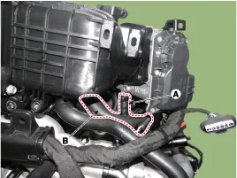
| 12. |
Remove the throttle body Cooling hose (A), PCSV hose (B).
|
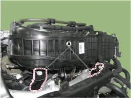
| 13. |
Remove the surge tank fixing bracket (A).
|
| 14. |
Remove the surge tank (A).
|

| 15. |
To install, reverse the removal procedure. |
Components 1. Surge tank2. VIS actuator
Components 1. Intake manifold
Other information:
Hyundai Genesis (DH) 2013-2016 Service Manual: Description and Operation
D
Hyundai Genesis (DH) 2013-2016 Service Manual: Photo Sensor Repair procedures
Inspection 1. Turn the ignition switch ON. 2. Connect the GDS. 3. Emit intensive light toward the photo sensor using a lamp, and check the output voltage change. 4. The voltage will rise with higher intensive light and fall with lower intensive light.
Categories
- Manuals Home
- Hyundai Genesis Owners Manual
- Hyundai Genesis Service Manual
- Components and Components Location
- Emission Control System
- Rain Sensor Repair procedures
- New on site
- Most important about car

Copyright © 2026 www.hgenesisdh.com - 0.024