Hyundai Genesis (DH): Smart Key System / Smart Key Diagnostic Repair procedures
Hyundai Genesis (DH) 2013-2016 Service Manual / Body Electrical System / Smart Key System / Smart Key Diagnostic Repair procedures
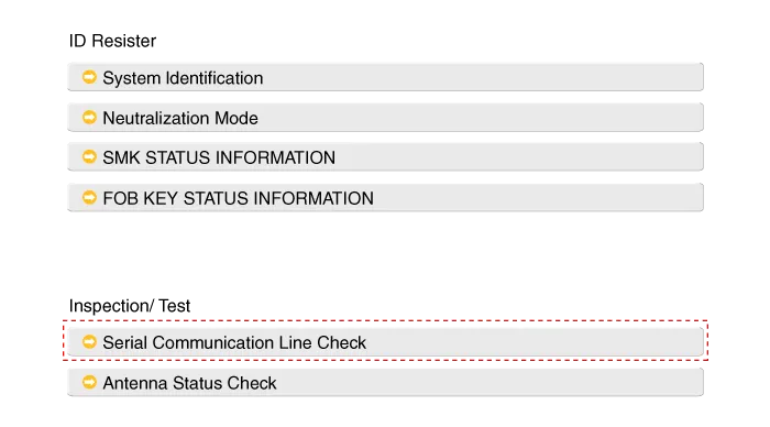
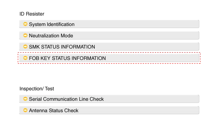
| Inspection |
Self Diagnosis With Scan Tool
It will be able to diagnose defects of SMART KEY system with
GDS quickly. GDS can operates actuator forcefully, input/output value
monitoring and self diagnosis.
The following three features will be major problem in SMART KEY system.
| 1. |
Problem in SMART KEY unit input. |
| 2. |
Problem in SMART KEY unit. |
| 3. |
Problem in SMART KEY unit output. |
So the following three diagnosis operates will be the major problem solution process.
| 1. |
SMART KEY unit Input problem : switch diagnosis |
| 2. |
SMART KEY unit problem : communication diagnosis |
| 3. |
SMART KEY unit Output problem : antenna and switch output diagnosis |
Switch Diagnosis
| 1. |
Connect the cable of GDS to the data link connector in driver side crash pad lower panel, turn the power on GDS. |
| 2. |
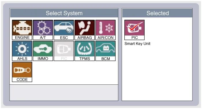
Select the vehicle model and then SMART KEY system.
|
| 3. |
Select the "SMART KEY unit". |
| 4. |
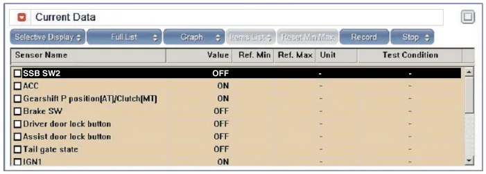
After IG ON, select the "Current data".
|
| 5. |
You can see the situation of each switch on scanner after connecting the "current data" process.
|
Communication Diagnosis With GDS (Self Diagnosis)
| 1. |
Communication diagnosis checks that the each linked components operates normal. |
| 2. |
Connect the cable of GDS to the data link connector in driver side crash pad lower panel. |
| 3. |
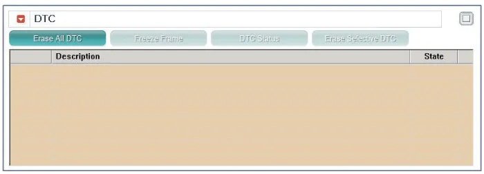
After IG ON, select the "DTC".
|
Antenna Actuation Diagnosis
| 1. |
Connect the cable of GDS to the data link connector in driver side crash pad lower panel. |
| 2. |
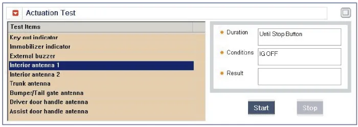
After IG ON, select the "ACTUATION TEST".
|
| 3. |
Set the smart key near the related antenna and operate it with a GDS.
|
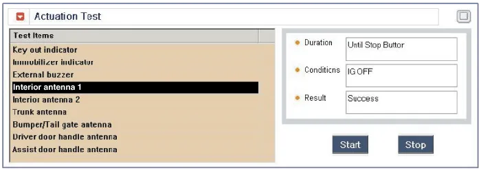
| 4. |
If the LED of smart key is blinking, the smart key is normal. |
| 5. |
If the LED of smart key is not blinking, check the voltage of smart key battery. |
| 6. |
Antenna actuation
|
Antenna Status Check
| 1. |
Connect the cable of GDS to the data link connector in driver side crash pad lower panel. |
| 2. |
Select the "Antenna Status Check".
|
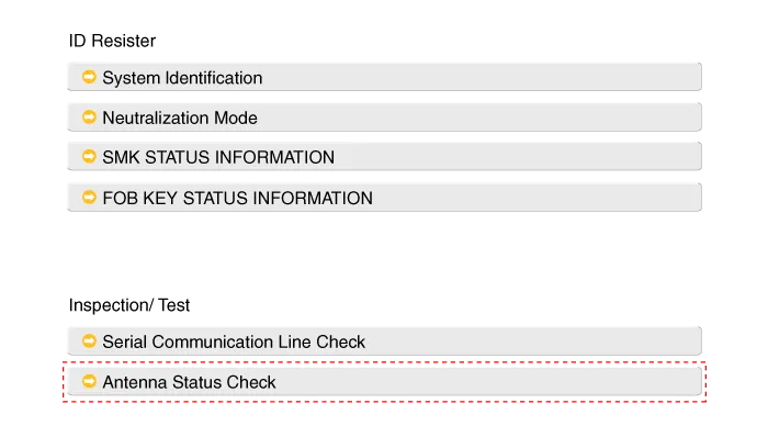
| 3. |
After IG ON, select the "Antenna Status Check".
|

| 4. |
Set the smart key near the related antenna and operate it with a GDS.
|
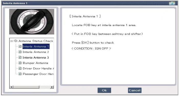
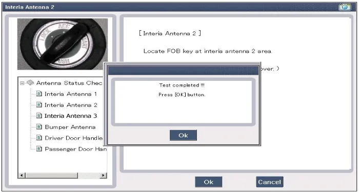
| 5. |
If the smart key runs normal , the related antenna, smart key(transmission, reception) and exterior receiver are normal. |
| 6. |
Antenna status
|
Serial Communication Status Check
| 1. |
Connect the cable of GDS to the data link connector in driver side crash pad lower panel. |
| 2. |
Select the "Serial Communication Line Check".
|
| 3. |
After IG ON, select the "Receiver Communication Line Check".
|
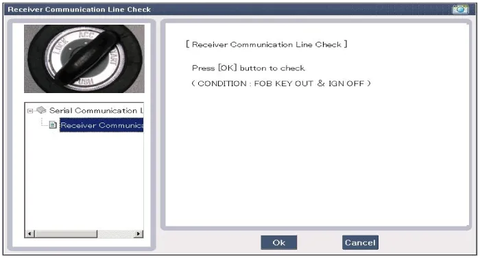
| 4. |
Check the serial communication line with a GDS. |
| 5. |
If the smart key runs normal, the communication of smart key unit and exterior receiver are normal. |
| 6. |
If the smart key runs abnormal, check the following items.
|
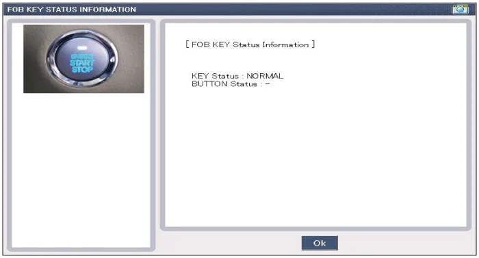
FOB Status Check
| 1. |
Connect the cable of GDS to the data link connector in driver side crash pad lower panel. |
| 2. |
After IG ON, select the "FOB KEY STATUS INFO".
|
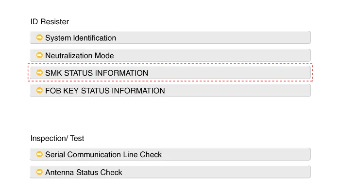
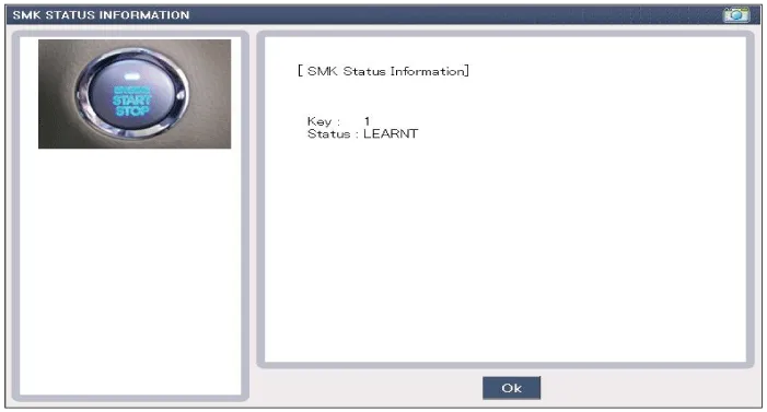
Smart Key Status Check
| 1. |
Connect the cable of GDS to the data link connector in driver side crash pad lower panel. |
| 2. |
After IG ON, select the "SMK STATUS INFO".
|
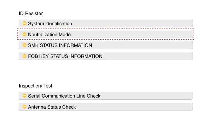
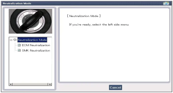
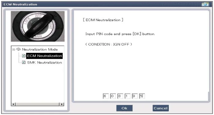
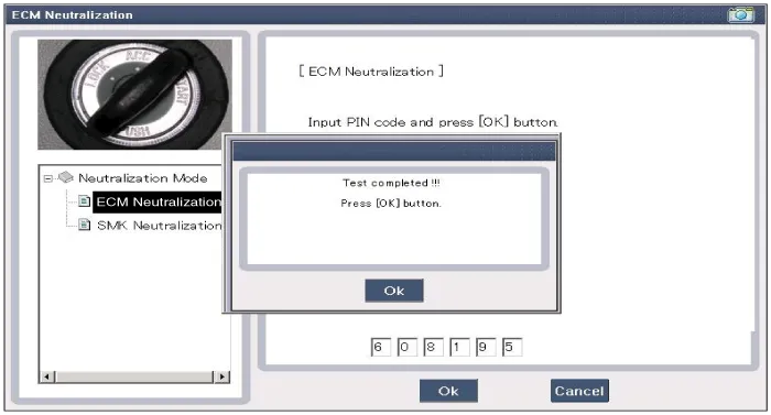
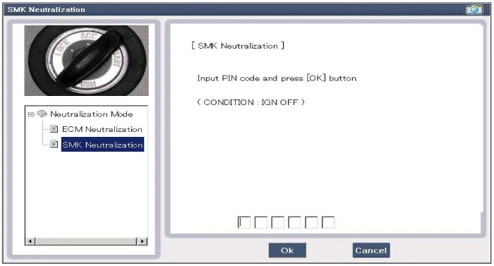
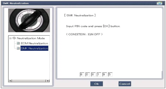
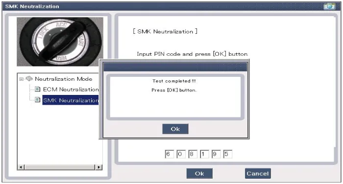
Neutralization Status Check
| 1. |
Connect the cable of GDS to the data link connector in driver side crash pad lower panel. |
| 2. |
After IG ON, select the "Neutralization mode".
|
Removal Smart Key Unit 1. Disconnect the negative (-) battery terminal. 2. Remove the driver crash pad lower panel. (Refer to Body - "Crash Pad Lower Panel") 3.
Other information:
Hyundai Genesis (DH) 2013-2016 Service Manual: Front Fog Lamps Repair procedures
Removal 1. Disconnect the negative (-) battery terminal. 2. Remove the front bumper. (Refer to Body - "Front Bumper Cover") 3. Disconnect the front fog lamp connector (A). 4. Remove the front fog lamp assembly (A) after loosening the mounting nut.
Hyundai Genesis (DH) 2013-2016 Service Manual: Blower Unit Components and Components Location
Component Location Components 1. Seal2. Intake Duct Case3. Intake Door4. Intake Actuator5. Intake Duct Case (A)6. Climate Control Air Filter7. Climate Control Air Filter Cover8. Cluster Ionizer9. Blower Upper Case10. Blower Lower Case11. Power Mosfet12.
Categories
- Manuals Home
- Hyundai Genesis Owners Manual
- Hyundai Genesis Service Manual
- Heating, Ventilation and Air Conditioning
- 4 Wheel Drive (AWD) System
- Front Door
- New on site
- Most important about car

Copyright © 2026 www.hgenesisdh.com - 0.0254