
Hyundai Genesis (DH): Blind Spot Detection system / Repair procedures
| Diagnosis With GDS |
| 1. |
BSD system defects can be quickly diagnosed with the GDS. GDS
operates actuator quickly to monitor, input/output value and self
diagnosis. |
| 2. |
Connect the cable of GDS to the data link connector in driver side crash pad lower panel, and turn on the GDS. |
| 3. |
Select the vehicle model and then BSD system. |
| 4. |
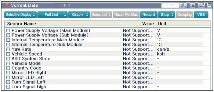
Select "Input/output monitoring", if you want to check current data of BSD system.
|
| 5. |
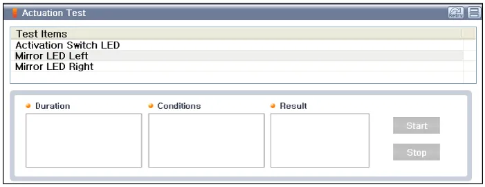
If you want to check each module operation forcefully, select "Actuation test".
|
Description BSD is a system that measures the speed of and distance from the following vehicles by using two magnetic wave radar sensors attached to the rear bumper, and detects any vehicle within the blind spot zone and gives off alarm (visual and auditory).
Circuit Diagram
Other information:
Hyundai Genesis (DH) 2013-2016 Service Manual: Auto Defogging Actuator Repair procedures
Inspection 1. Turn the ignition switch OFF. 2. Disconnect the auto defogging connector. 3. Verify that the auto defogging actuator operates to the open position when connecting 12V to terminal 3 and grounding terminal 4. Verify that the auto defogging actuator operates to the close position when connected in reverse.
Hyundai Genesis (DH) 2013-2016 Service Manual: Intake Actuator Repair procedures
Inspection 1. Turn the ignition switch OFF. 2. Disconnect the intake actuator connector. 3. Verify that the intake actuator operates to the fresh position when connecting 12V to terminal 3 and grounding terminal 4. Verify that the intake actuator operates to the recirculation position when connected in reverse.
Categories
- Manuals Home
- Hyundai Genesis Owners Manual
- Hyundai Genesis Service Manual
- Evaporative Emission Control System
- 4 Wheel Drive (AWD) System
- Starter Repair procedures
- New on site
- Most important about car
