Hyundai Genesis (DH): Seat Electrical / Seat heater switch Schematic Diagrams
Hyundai Genesis (DH) 2013-2016 Service Manual / Body Electrical System / Seat Electrical / Seat heater switch Schematic Diagrams
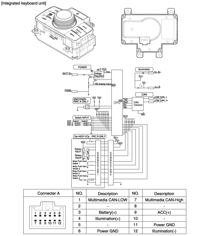
| Circuit Diagram |
Removal Front Seat 1. Disconnect the battery (-)terminals. 2. Remove the floor console upper cover. (Refer to Body - "Floor Console Assembly") 3.
Other information:
Hyundai Genesis (DH) 2013-2016 Service Manual: PGS Unit (Back & Blinde Unit) Schematic Diagrams
C
Hyundai Genesis (DH) 2013-2016 Service Manual: In-car Sensor Description and Operation
Description An in-car air temperature sensor is located in the crash pad lower panel. The sensor contains a thermistor which measures the temperature of the cabin. The signal determined by the resistance value which changes in accordance with perceived inside temperature, is delivered to the heater control unit and according to this signa
Categories
- Manuals Home
- Hyundai Genesis Owners Manual
- Hyundai Genesis Service Manual
- Suspension System
- Smart Cruise Control Unit Repair procedures
- Restraint
- New on site
- Most important about car

Copyright © 2026 www.hgenesisdh.com - 0.0313