Hyundai Genesis (DH): Button Engine Start System / Schematic Diagrams
Hyundai Genesis (DH) 2013-2016 Service Manual / Body Electrical System / Button Engine Start System / Schematic Diagrams
| Circuit Diagram (1) |
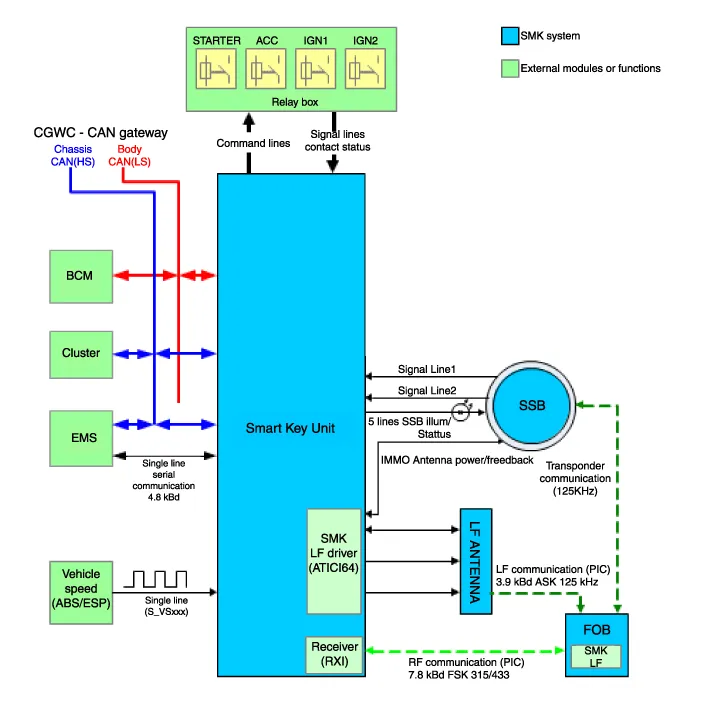
Component Location 1. Start Stop Button(SSB)2. FOB key3. Trunk lid switch4. Body control module (BCM)5. Interior antenna 16. Interior antenna 27.
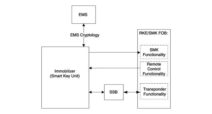
Description System Overview The System offers the following features: - Changing the state of engine ignition and power by using the start button.
Other information:
Hyundai Genesis (DH) 2013-2016 Service Manual: Description and Operation
D
Hyundai Genesis (DH) 2013-2016 Service Manual: Photo Sensor Description and Operation
Description The photo sensor is located in the right side of the inside rearview mirror. he integrated rain sensor is located in the right side of the inside rearview mirror. The integrated rain sensor is a multifunctional sensor which combines the photo sensor and auto light sensor, and has a built-in photovoltaic diode (for detecting t
Categories
- Manuals Home
- Hyundai Genesis Owners Manual
- Hyundai Genesis Service Manual
- Description and Operation
- Starter Repair procedures
- 4 Wheel Drive (AWD) System
- New on site
- Most important about car

Copyright © 2026 www.hgenesisdh.com - 0.0314