Hyundai Genesis (DH): Rear Driveshaft Assembly / Rear Driveshaft (VL-VL TYPE) Repair procedures
Hyundai Genesis (DH) 2013-2016 Service Manual / Driveshaft and axle / Rear Driveshaft Assembly / Rear Driveshaft (VL-VL TYPE) Repair procedures
| Replacement |
[LAMMDA]
| 1. |
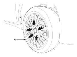
Loosen the wheel nuts slightly. Raise the vehicle, and make sure it is securely supported. |
| 2. |
Remove the rear wheel and tire from the rear hub.
|

| 3. |
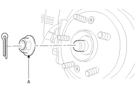
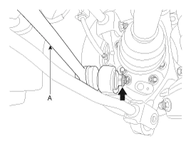
Remove the split pin, then remove castle nut (A) and washer from the front hub.
|
| 4. |
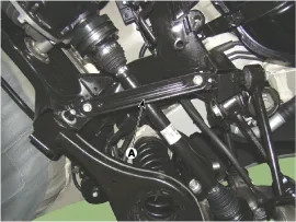
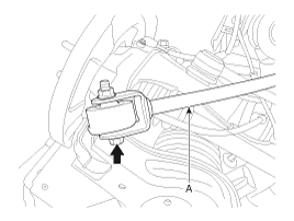
Remove the bracket (A).
|

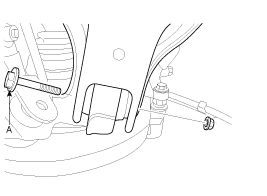
| 5. |
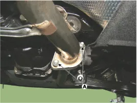
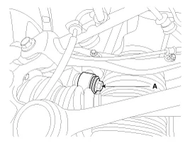
Loosen the mounting bolt (A).
|
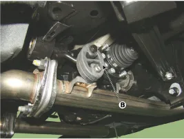
| 6. |
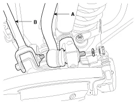
Disconnect the rubber hanger (B), (C) and then remove the muffler.
|
| 7. |
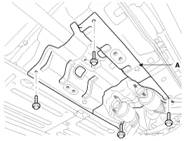
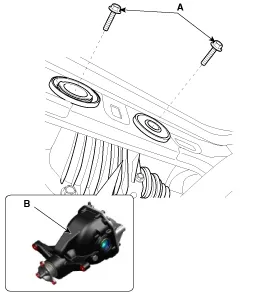
Loosen the mount bolts and then aluminum cover (A).
|
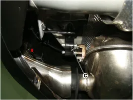
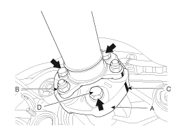
| 8. |
After making a match mark (C) on the rubber coupling (A) and
rear differential companion (B), remove the propeller shaft mounting
bolts (D).
|
| 9. |
Remove the differential carrier assembly mount bolts (B).
|

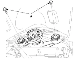
| 10. |
Loosen the bolts and then remove the rear driveshaft.
|

| 11. |
Installation is the reverse order of removal. |
[TAU]
| 1. |
Loosen the wheel nuts slightly. Raise the vehicle, and make sure it is securely supported. |
| 2. |
Remove the rear wheel and tire from the rear hub.
|
| 3. |
Remove the split pin, then remove castle nut (A) and washer from the front hub under applying the break.
|
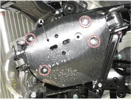
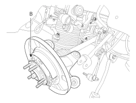
| 4. |
Loosen the bolts and remove the cover (A).
|
| 5. |
Remove the bracket (A).
|
| 6. |
Remove the parking brake cable.
(Refer to Brake System - "Parking Brake Assembly") |
| 7. |
Remove the wheel speed sensor (A) from the rear axle carrier.
|

| 8. |
Loosen the mounting nut and remove the assist arm (A) using a SST (09568-2J100).
|

| 9. |
Loosen the mounting bolt and remove the trailing arm (A).
|
| 10. |
Remove the shock absorber mounting bolt (A).
|
| 11. |
Remove the rear upper arm front (B) & rear upper arm rear (A) link.
|

| 12. |
Remove lower arm mount bolt (A) from rear axle carrier assembly (B).
|
| 13. |
Remove the rear drive shaft. |
Component Location 1. Rear driveshaft LH2. Rear differential carrier assembly3. Rear driveshaft RH
Other information:
Hyundai Genesis (DH) 2013-2016 Service Manual: Troubleshooting
Troubleshooting Problem Symptoms Table Before replacing or repairing air conditioning components, first determine if the malfunction is due to the refrigerant charge, air flow or compressor. Use the table below to help you find the cause of the problem.
Hyundai Genesis (DH) 2013-2016 Service Manual: Compressor Description and Operation
Description The compressor is the power unit of the A/C system. It is located on the side of engine block and driven by a V-belt of the engine. The compressor changes low-pressure and low-temperature refrigerant gas into high-pressure and high-temperature refrigerant gas.
Categories
- Manuals Home
- Hyundai Genesis Owners Manual
- Hyundai Genesis Service Manual
- Starter Repair procedures
- Active Air Flap(AAF) Repair procedures
- Heating, Ventilation and Air Conditioning
- New on site
- Most important about car

Copyright © 2026 www.hgenesisdh.com - 0.024