Hyundai Genesis (DH): IMS(Integrated Memory System) / Memory power seat unit Schematic Diagrams
| Circuit Diagram |
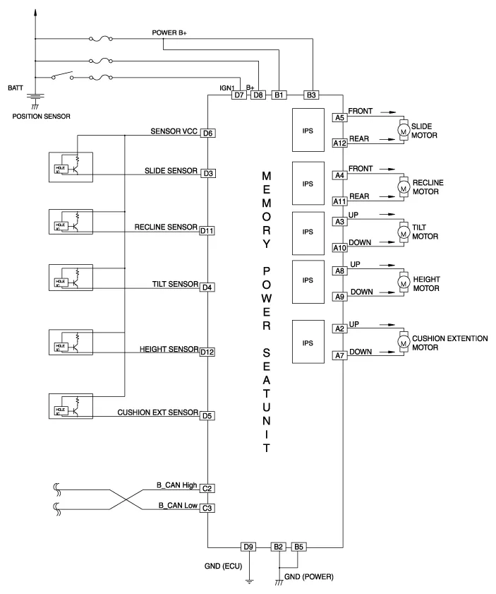
Components NOConnecter AConnecter BConnecter CConnecter D1-B+ (Power)--2Cushion extension moter(Front)GND (Power)B CAN High-3Front tilt motor(UP)B+ (Power)B CAN LowSlide hall sensor4Back motor(Front)--Tilt hall sensor5Slide motor(Front)GND (Power)-Cushion ext hall sensor6-?-Sensor VCC7Cushion extends motor(Rear)-IGN18 Rear height sensor(UP)-B+ (ECU)9 Rear height sensor(Down)-GND (ECU)10Front tilt motor(Down)--11Back motor(Rear)-Recline hall sensor12Slide Moter(Rear)-Height hall sensor13?--14--15--16--17-?18-19-20-
Removal 1. Disconnect the negative (-) battery terminal. 2. Remove the front seat. (Refer to Body - "Front Seat Assembly") 3. Driver settings menu (USM) is Off, 4.
Other information:
Hyundai Genesis (DH) 2013-2016 Service Manual: LKAS Unit Repair procedures
Removal 1. Disconnect the negative (-) battery terminal. 2. Remove the mirror wiring cover (A) and rain sensor cover (B). 3. Remove the LKAS unit connector (A). 4. Remove the LKAS unit after disengaging the mounting bracket (A). Installation 1.
Hyundai Genesis (DH) 2013-2016 Service Manual: Repair procedures
Diagnosis With GDS 1. BSD system defects can be quickly diagnosed with the GDS. GDS operates actuator quickly to monitor, input/output value and self diagnosis. 2. Connect the cable of GDS to the data link connector in driver side crash pad lower panel, and turn on the GDS.
Categories
- Manuals Home
- Hyundai Genesis Owners Manual
- Hyundai Genesis Service Manual
- Body Electrical System
- Parking Assist Sensor Repair procedures
- Starter Repair procedures
- New on site
- Most important about car
