Hyundai Genesis (DH): IMS(Integrated Memory System) / Memory power seat unit Repair procedures
Hyundai Genesis (DH) 2013-2016 Service Manual / Body Electrical System / IMS(Integrated Memory System) / Memory power seat unit Repair procedures
| Removal |
| 1. |
Disconnect the negative (-) battery terminal. |
| 2. |
Remove the front seat.
(Refer to Body - "Front Seat Assembly") |
| 3. |
Driver settings menu (USM) is Off,
|
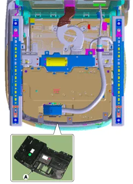
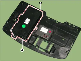
| 4. |
Loosen the mounting screws (2) and remove the IMS unit (A).
|
| Installation |
| 1. |
Install the memory power seat unit. |
| 2. |
Install the front sheet inner cover . |
| 3. |
Install the Driver's seat assembly. |
| 4. |
Connect the negative (-) battery terminal. |
Circuit Diagram
Other information:
Hyundai Genesis (DH) 2013-2016 Service Manual: Components and Components Location
C
Hyundai Genesis (DH) 2013-2016 Service Manual: Auto Head Lamp Leveling Unit Description and Operation
Description According to driving environment and loading state of vehicle, head lamp lighting direction is changed to keep the driver's visibility range and to protect the driver's vision from glare, aiming at safety driving. Sensor integrated ECU mounting on the rear center arm drives the actuator mounting on the head lamp since sens
Categories
- Manuals Home
- Hyundai Genesis Owners Manual
- Hyundai Genesis Service Manual
- Smart Cruise Control Unit Repair procedures
- Transmission Control Module (TCM) Repair procedures
- Brake System
- New on site
- Most important about car

Copyright © 2026 www.hgenesisdh.com - 0.0273