
Hyundai Genesis (DH): Automatic Transmission Control System / Transmission Control Module (TCM) Schematic Diagrams
Hyundai Genesis (DH) 2013-2016 Service Manual / Automatic Transmission System (SBC) / Automatic Transmission Control System / Transmission Control Module (TCM) Schematic Diagrams
| 1. TCM Connector and Terminal Function |
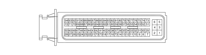
| 2. TCM Terminal Function |
Connector
| Pin | Description | Pin | Description |
| 1 | Battery power | 48 | - |
| 2 | Battery power | 49 | - |
| 3 | Power(IG 1) | 50 | 27 Brake control solenoid valve |
| 4 | Ground | 51 | - |
| 5 | Ground | 52 | ON/OFF solenoid valve |
| 6 | Ground | 53 | - |
| 7 | - | 54 | Input speed sensor signal |
| 8 | - | 55 | Middle speed sensor signal |
| 9 | - | 56 | Output speed sensor signal |
| 10 | - | 57 | - |
| 11 | - | 58 | - |
| 12 | - | 59 | - |
| 13 | Inhibitor switch signal "S1" | 60 | - |
| 14 | Oil temperature sensor (+) | 61 | Sports mode select switch |
| 15 | - | 62 | - |
| 16 | Sports mode up switch | 63 | - |
| 17 | Sports mode down switch | 64 | - |
| 18 | - | 65 | CAN communication line (LOW) |
| 19 | - | 66 | - |
| 20 | - | 67 | - |
| 21 | Inhibitor switch signal "S2" | 68 | - |
| 22 | Inhibitor switch signal "S4" | 69 | - |
| 23 | Inhibitor switch signal "S3" | 70 | Solenoid supply power 2 |
| 24 | - | 71 | - |
| 25 | - | 72 | - |
| 26 | - | 73 | Solenoid supply power (4&OD/C,35R/C,6/C,L/P) |
| 27 | - | 74 | - |
| 28 | - | 75 | - |
| 29 | Solenoid supply power(UD/C,27/B,8LR/B,D/C) | 76 | - |
| 30 | Input speed sensor power | 77 | - |
| 31 | Middle speed sensor power | 78 | - |
| 32 | - | 79 | - |
| 33 | - | 80 | - |
| 34 | - | 81 | - |
| 35 | - | 82 | - |
| 36 | - | 83 | - |
| 37 | - | 84 | - |
| 38 | Oil temperature sensor (-) | 85 | CCP CAN Low |
| 39 | - | 86 | CCP CAN High |
| 40 | - | 87 | CAN communication line (High) |
| 41 | 35R Clutch control solenoid valve | 88 | - |
| 42 | 8LR Brake control solenoid valve | 89 | - |
| 43 | Underdrive clutch control solenoid valve | 90 | - |
| 44 | 6Speed clutch control solenoid valve | 91 | - |
| 45 | Line pressure control solenoid valve | 92 | - |
| 46 | Damper clutch control solenoid valve | 93 | Output speed sensor power |
| 47 | 4&OD Clutch control solenoid valve | 94 | - |
| 3. TCM Terminal input/output signal |
| Pin | Description | Condition | Input/Output Value | |
| Type | Level | |||
| 1 | Battery power | ON | Power | 0V/Battery voltage level |
| 2 | OFF | 9V < Battery voltage level < 16V | ||
| 3 | Power (IG 1) | ON | Input | Battery voltage level |
| OFF | 0V voltage level | |||
| 4 | Ground | - | Ground | 0V(GND level) |
| 5 | Ground | - | Ground | 0V(GND level) |
| 6 | Ground | - | Ground | 0V(GND level) |
| 7 | - | ON | Output | About 1V |
| OFF | Battery voltage level | |||
| 8 | - | - | Output | 0V/Battery voltage level |
| 9V < Battery voltage level <16V | ||||
| 9 | - | - | - | - |
| 10 | - | ON | Pulse input | About 9V~11V voltage level |
| OFF | 0V voltage level | |||
| 11 | - | - | - | - |
| 12 | - | - | - | - |
| 13 | Inhibitor switch signal "S1" | ON | Input | Battery voltage level |
| OFF | 0V(GND) | |||
| 14 | Oil temperature sensor (+) | - | Input | Maximum 5V voltage level |
| 15 | - | - | - | - |
| 16 | Sports mode up switch | ON | Input | 0V(GND) |
| OFF | Battery voltage level | |||
| 17 | Sports mode down switch | ON | Input | 0V(GND) |
| OFF | Battery voltage level | |||
| 18 | - | - | Input | 0V/Battery voltage level |
| 19 | - | - | - | - |
| 20 | - | - | - | - |
| 21 | Inhibitor switch signal "S2" | ON | Input | Battery voltage level |
| OFF | 0V(GND) | |||
| 22 | Inhibitor switch signal "S4" | ON | Input | Battery voltage level |
| OFF | 0V(GND) | |||
| 23 | Inhibitor switch signal "S3" | ON | Input | Battery voltage level |
| OFF | 0V(GND) | |||
| 24 | - | - | - | - |
| 25 | - | - | - | - |
| 26 | - | - | Output | 0V/Battery voltage level |
| 9V < Battery voltage level <16V | ||||
| 27 | - | - | - | - |
| 28 | - | - | Output | 0V/Battery voltage level |
| 9V < Battery voltage level <16V | ||||
| 29 | Solenoid supply power (UD/C,27/B,8LR/B,D/C) | - | Power | Battery voltage level |
| 9V < Battery voltage level <16V | ||||
| 30 | Input speed sensor power | ON | Output | About 9V voltage level |
| OFF | 0V | |||
| 31 | Middle speed sensor power | ON | Output | About 9V voltage level |
| OFF | 0V | |||
| 32 | - | - | - | - |
| 33 | - | - | - | - |
| 34 | - | - | - | - |
| 35 | - | - | - | - |
| 36 | - | - | - | - |
| 37 | - | - | - | - |
| 38 | Oil temperature sensor (-) | - | Input | Minimum 0V voltage level |
| 39 | - | - | - | - |
| 40 | - | - | - | - |
| 41 | 35R Clutch control solenoid valve | - | Output | 0V/Battery voltage level |
| 9V < Battery voltage level <16V | ||||
| 42 | 8LR Brake control solenoid valve | - | Output | 0V/Battery voltage level |
| 9V < Battery voltage level <16V | ||||
| 43 | Underdrive clutch control solenoid valve | - | Output | 0V/Battery voltage level |
| 9V < Battery voltage level <16V | ||||
| 44 | 6Speed clutch control solenoid valve | - | Output | 0V/Battery voltage level |
| 9V < Battery voltage level <16V | ||||
| 45 | Line pressure control solenoid valve | - | Output | 0V/Battery voltage level |
| 9V < Battery voltage level <16V | ||||
| 46 | Damper clutch control solenoid valve | - | Output | 0V/Battery voltage level |
| 9V < Battery voltage level <16V | ||||
| 47 | 4&OD Clutch control solenoid valve | - | Output | 0V/Battery voltage level |
| 9V < Battery voltage level <16V | ||||
| 48 | - | - | - | - |
| 49 | - | - | - | - |
| 50 | 27 Brake control solenoid valve | - | Output | 0V/Battery voltage level |
| 9V < Battery voltage level <16V | ||||
| 51 | - | - | - | - |
| 52 | ON/OFF solenoid valve | - | Output | 0V/Battery voltage level |
| 9V < Battery voltage level <16V | ||||
| 53 | - | ON | Output | 0V |
| OFF | Battery voltage level | |||
| 54 | Input speed sensor signal | ? | Pulse input | Low : About 0.7V, High : 1.4V |
| NTU1 | ? | Maximum/Minimum Frequency : 9kHz/0Hz | ||
| 55 | Middle speed sensor signal | ? | PulseInput | Low : About 0.7V, High : 1.4V |
| NTU2 | ? | Maximum/Minimum Frequency : 9kHz/0Hz | ||
| 56 | Output speed sensor signal | ? | PulseInput | Low : About 0.7V, High : 1.4V |
| NAB | ? | Maximum/Minimum Frequency : 9kHz/0Hz | ||
| 57 | - | - | - | - |
| 58 | - | - | - | - |
| 59 | - | - | - | - |
| 60 | - | - | - | - |
| 61 | Sports mode select switch | Sports mode | Input | 0V/Battery voltage level |
| Other | 9V < Battery voltage level <16V | |||
| 62 | - | - | - | - |
| 63 | - | - | - | - |
| 64 | - | - | - | - |
| 65 | CAN communication line (LOW) | - | - | - |
| 66 | - | - | - | - |
| 67 | - | - | - | - |
| 68 | - | - | - | - |
| 69 | - | - | - | - |
| 70 | Solenoid supply power 2 | - | Power | Battery voltage level |
| 9V < Battery voltage level <16V | ||||
| 71 | ? | - | - | - |
| 72 | ? | - | - | - |
| 73 | Solenoid supply power (4&OD/C,35R/C,6/C,L/P) | - | Power | Battery voltage level |
| 9V < Battery voltage level <16V | ||||
| 74 | ? | - | - | - |
| 75 | ? | - | - | - |
| 76 | ? | - | - | - |
| 77 | ? | - | - | - |
| 78 | ? | - | - | - |
| 79 | ? | - | - | - |
| 80 | ? | - | - | - |
| 81 | ? | - | - | - |
| 82 | ? | - | - | - |
| 83 | ? | - | - | - |
| 84 | ? | - | - | - |
| 85 | ? | - | - | - |
| 86 | ? | - | - | - |
| 87 | CAN communication line (High) | - | - | - |
| 88 | ? | ? | ? | ? |
| 89 | ? | ? | ? | ? |
| 90 | ? | ? | ? | ? |
| 91 | ? | ? | ? | ? |
| 92 | ? | - | - | - |
| 93 | Output speed sensor power | ON | Output | About 9V voltage level |
| OFF | 0V | |||
| 94 | ? | ? | ? | ? |
Description Transmission Control Module (TCM) plays a role of the brain for the automatic transmission. The module receives and processes signals from various sensors and implements a wide range of Transmission controls to ensure optimal driving conditions for the driver.
Removal 1. Turn ignition switch OFF and disconnect the negative (-) battery cable. 2. Remove the cover (A). 3. Disconnect the ECM connector (A), TCM connector (B) and IDB connector (C).
Other information:
Hyundai Genesis (DH) 2013-2016 Service Manual: Components and Components Location
C
Hyundai Genesis (DH) 2013-2016 Service Manual: Console Temperature Control Actuator Repair procedures
Inspection 1. Turn the ignition switch OFF. 2. Disconnect the console temperature control actuator connector. 3. Verify that the console temperature control actuator operates to the defrost mode when connecting 12V to terminal 3 and grounding terminal 4.
Categories
- Manuals Home
- Hyundai Genesis Owners Manual
- Hyundai Genesis Service Manual
- Description and Operation
- Description and Operation
- Evaporative Emission Control System
- New on site
- Most important about car

Copyright В© 2026 www.hgenesisdh.com - 0.0274