
Hyundai Genesis (DH): Timing System / Timing Chain Components and Components Location
| Components |
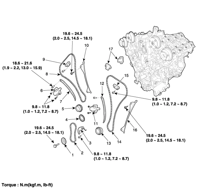
| 1. Oil pump sprocket 2. Oil pump chain 3. Oil pump tensioner assembly 4. Crankshaft oil pump sprocket 5. Crankshaft RH chain sprocket 6. RH timing chain auto tensioner | 7. RH timing chain tensioner arm 8. RH timing chain 9. RH cam to cam guide 10. RH timing chain guide 11. LH timing chain auto tensioner 12. LH timing chain tensioner arm | 13. Crankshaft LH chain sprocket 14. LH timing chain 15. LH cam to cam guide 16. LH timing chain guide 17. tensioner adapter |
Removal 1. Remove the lower oil pan. (Refer to Lubrication System - "Oil Pan") 2. Drain the coolant. (Refer to Cooling System - "Coolant") 3.
Removal 1. Set No.1 cylinder to top dead center (TDC)/compression. (1) Turn the crankshaft pulley clockwise and align its groove with the timing mark "T" of the lower timing chain cover.
Other information:
Hyundai Genesis (DH) 2013-2016 Service Manual: Auto Head Lamp Leveling Unit Repair procedures
Inspection 1. Ignition "ON". 2. Turn on the head lamp switch. 3. Check that the aim of the head lamp changes smoothly when the head lamp leveling device switch is turned on. 4. If it does not operate well, check the connector and terminals to make sure that they are connected.
Hyundai Genesis (DH) 2013-2016 Service Manual: Console Temperature Control Actuator Repair procedures
Inspection 1. Turn the ignition switch OFF. 2. Disconnect the console temperature control actuator connector. 3. Verify that the console temperature control actuator operates to the defrost mode when connecting 12V to terminal 3 and grounding terminal 4.
Categories
- Manuals Home
- Hyundai Genesis Owners Manual
- Hyundai Genesis Service Manual
- Components and Components Location
- Body (Interior and Exterior)
- Engine Mechanical System
- New on site
- Most important about car
