Hyundai Genesis (DH): Starting System / Starter Schematic Diagrams
Hyundai Genesis (DH) 2013-2016 Service Manual / Engine Electrical System / Starting System / Starter Schematic Diagrams
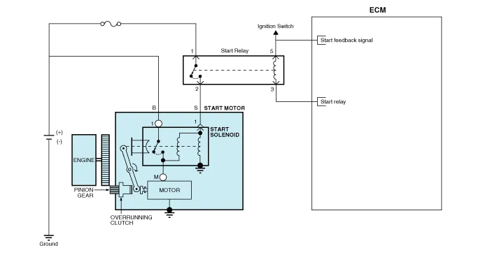
| Circuit Diagram |
Components 1. Front bracket2. Planet gear shaft assembly3. Lever4. Lever packing5. Magnet switch6. Planet gear7. Shield8. Armature assembly9. York assembly10.
Removal 1. Turn ignition switch OFF and disconnect the negative (-) battery cable. 2. Remove the RH engine manifold. (Refer to Engine Mechanical System - "Exhaust Manifold") 3.
Other information:
Hyundai Genesis (DH) 2013-2016 Service Manual: Components and Components Location
C
Hyundai Genesis (DH) 2013-2016 Service Manual: Refrigerant Line Repair procedures
Replacement 1. Discharge refrigerant from refrigeration system. 2. Replace any faulty tubes or hoses. Cap the open fittings immediately to keep moisture or dirt out of the system. 3. Tighten the bolt or nut joint to the specified torque.
Categories
- Manuals Home
- Hyundai Genesis Owners Manual
- Hyundai Genesis Service Manual
- Heating, Ventilation and Air Conditioning
- Brake System
- Description and Operation
- New on site
- Most important about car

Copyright © 2026 www.hgenesisdh.com - 0.0223