Hyundai Genesis (DH): Seat Electrical / Power seat control switch Schematic Diagrams
Hyundai Genesis (DH) 2013-2016 Service Manual / Body Electrical System / Seat Electrical / Power seat control switch Schematic Diagrams
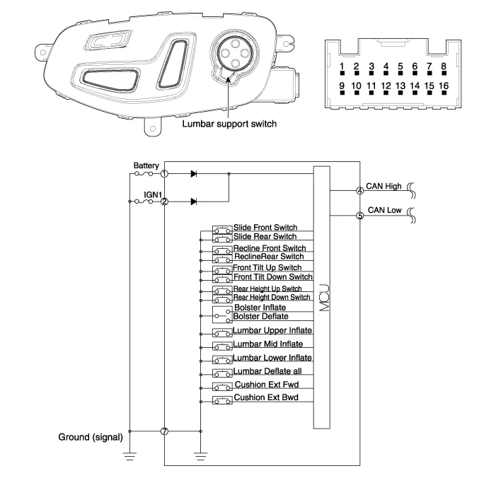
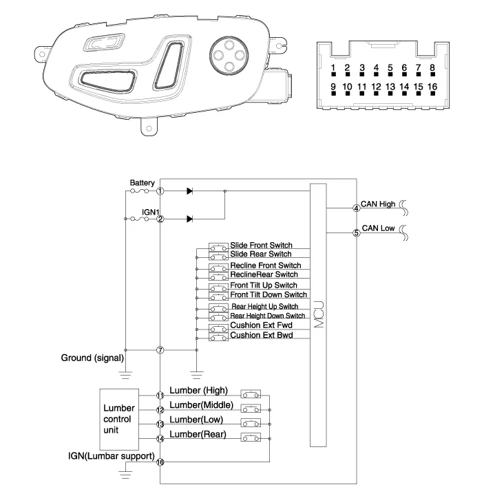
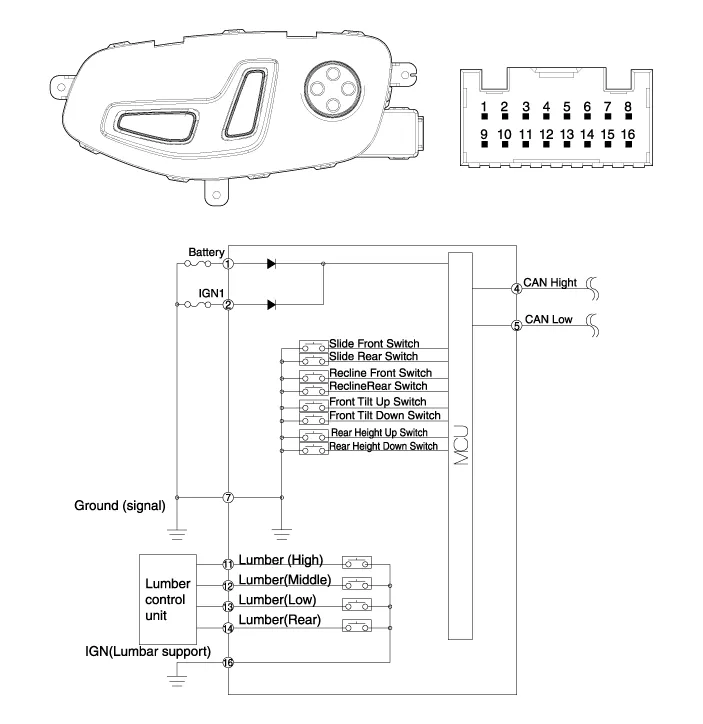
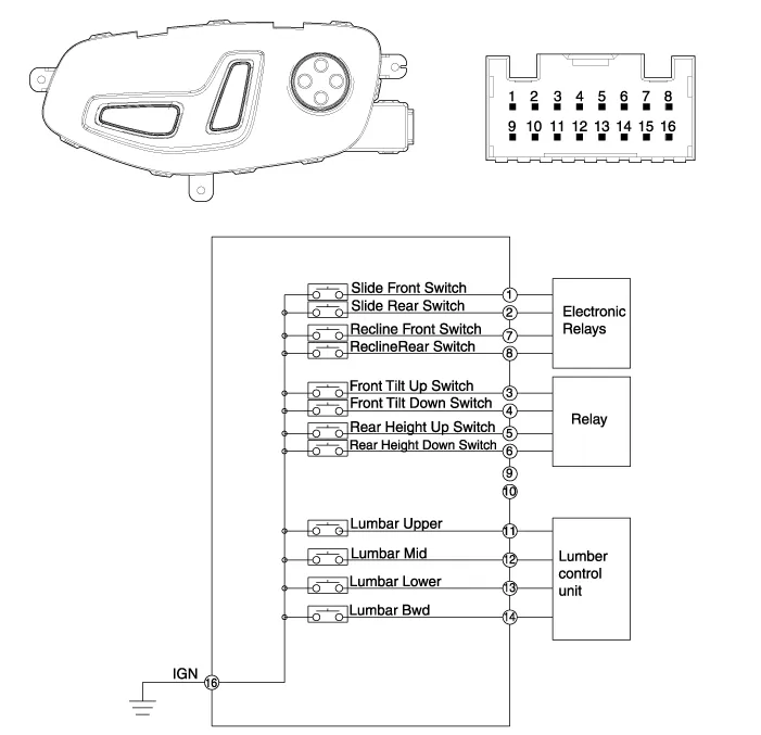
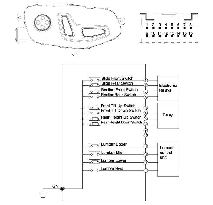
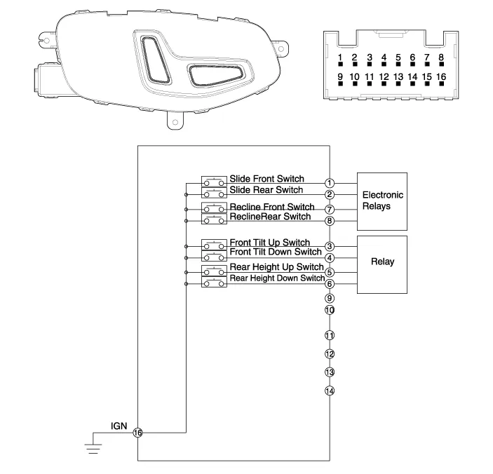
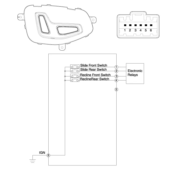
| Circuit Diagram |
| [A type of driver's seat] |
| [B type of driver's seat] |
| [C type of driver's seat] |
| [D type of driver's seat] |
| [A type Assist] |
| [B type Assist] |
| [C type Assist] |
Removal Air lumbar support and bolster assembly 1. Disconnect the negative (-) battery terminal. 2. Remove the front seat back cover. (Refer to Body - "Front Seat Back Cover") 3.
Inspection 1. Power seat switch sends/receives signals via CAN communication so it is impossible to check the electric current of switch components.
Other information:
Hyundai Genesis (DH) 2013-2016 Service Manual: Description and Operation
Description Control Function This system supports 2 kinds of main function. (Rear video display function, Expected trace of wheels display function) The Rear video display and the expected trace of wheels display operate according to Vehicle speed condition and Gear position.
Hyundai Genesis (DH) 2013-2016 Service Manual: CO2 Sensor Repair procedures
R
Categories
- Manuals Home
- Hyundai Genesis Owners Manual
- Hyundai Genesis Service Manual
- Body (Interior and Exterior)
- Steering System
- Active Air Flap(AAF) Repair procedures
- New on site
- Most important about car

Copyright © 2026 www.hgenesisdh.com - 0.0254