Hyundai Genesis (DH): Seat Electrical / Lumber Support Units Repair procedures
Hyundai Genesis (DH) 2013-2016 Service Manual / Body Electrical System / Seat Electrical / Lumber Support Units Repair procedures
| Removal |
| Air lumbar support and bolster assembly |
| 1. |
Disconnect the negative (-) battery terminal. |
| 2. |
Remove the front seat back cover.
(Refer to Body - "Front Seat Back Cover") |
| 3. |
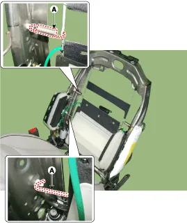
Remove the Front seat back (A) after loosening the mounting clip.
|
| 4. |
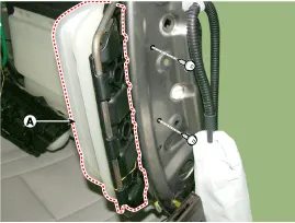
Unscrew the fixing screws and remove the air bolsters.
|
| 5. |
Remove the Air Lumber & bolster assembly after loosening the mounting clip.
|
| Installation |
| 1. |
Install the Air lumbar support and bolster assembly |
| 2. |
Install the front seat back cover. |
| 3. |
Check the air lumbar support and bolster assembly system for normal operation. |
| Inspection |
| 1. |
In the body electrical system, failure can be quickly diagnosed by using the vehicle diagnostic system (GDS).
The diagnostic system (GDS) provides the following information.
|
| 2. |
Select the 'Car model' and the system to be checked in order to check the vehicle with the tester. |
| 3. |
Select the module to check the air lumbar support and bolster system.
Select "BCM" and "Driver seat and assistant seat door module
(Air lumbar support and bolster system)" to check the driver seat or
assistant door module (Air lumbar support and bolster system). |
| 4. |
Select the "Current data" menu to search the current state of the input/output data.
The input/output data for the sensors corresponding to the
driver seat or assistant door module (Air lumbar support and bolster
system) can be checked. |
| 5. |
To forcibly actuate the input value of the module to be checked, select option "Actuation test". |
Air lumbar support
| 1. |
Disconnect the negative (-) battery terminal. |
| 2. |
Remove the seat back cover.
(Refer to Body - "Front Seat Back Cover") |
| 3. |
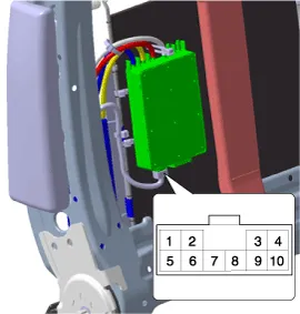
Remove the Air Lumber & Bolster unit connector.
|
| 4. |
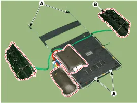
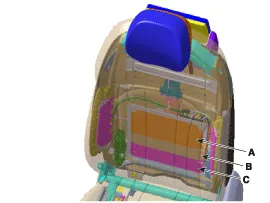
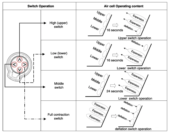
After supplying power to the air pump and voltage to each switch, check the air lumbar support for normal operation.
A. Air Pack(High)
B. Air Pack(Middle)
C. Air Pack(Low)
|
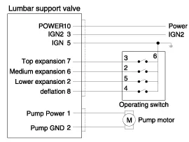
Component Location Air lumbar support & bolster assembly Mechanical lumbar support assembly
Circuit Diagram [A type of driver's seat] [B type of driver's seat] [C type of driver's seat] [D type of driver's seat] [A type Assist] [B type Assist] [C type Assist]
Categories
- Manuals Home
- Hyundai Genesis Owners Manual
- Hyundai Genesis Service Manual
- Engine Electrical System
- 4 Wheel Drive (AWD) System
- General Information
- New on site
- Most important about car

Copyright © 2026 www.hgenesisdh.com - 0.0289