Hyundai Genesis (DH): Seat Electrical / Power seat control switch Repair procedures
Hyundai Genesis (DH) 2013-2016 Service Manual / Body Electrical System / Seat Electrical / Power seat control switch Repair procedures
| Inspection |
| 1. |
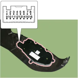
Power seat switch sends/receives signals via CAN
communication so it is impossible to check the electric current of
switch components.
|
| 2. |
Inspect the power seat system using GDS.
|

| Removal |
| 1. |
Disconnect the battery terminals(-). |
| 2. |
Remove the front seat shield outer cover.
(Refer to Body - "Front Seat Shield Outer Cover" )
|

| 3. |
Loosen the screws and remove the electric seat control switch (A).
|

| Installation |
| 1. |
Install the Electric seat control switch |
| 2. |
Install the front seat shield outer cover |
| 3. |
Connect the battery terminals. |
Circuit Diagram [A type of driver's seat] [B type of driver's seat] [C type of driver's seat] [D type of driver's seat] [A type Assist] [B type Assist] [C type Assist]
Categories
- Manuals Home
- Hyundai Genesis Owners Manual
- Hyundai Genesis Service Manual
- Front Door
- Parking Assist Sensor Repair procedures
- Starter Repair procedures
- New on site
- Most important about car

Copyright © 2026 www.hgenesisdh.com - 0.023