Hyundai Genesis (DH): Parking Brake System / Parking Brake Assembly Repair procedures
Hyundai Genesis (DH) 2013-2016 Service Manual / Brake System / Parking Brake System / Parking Brake Assembly Repair procedures
| Removal |
Parking Brake Pedal
| 1. |
Remove the crash pad lower panel.
(Refer to Body - "Crash Pad") |
| 2. |
Remove the IPM after removing the nut and connector.
(Refer to Body Electrical System - "BCM") |
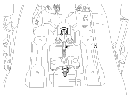
| 3. |
Disconnect the parking brake switch connector (A).
|
| 4. |
Remove the parking brake pedal mounting bolts and nut (B), then remove the parking brake pedal.
|
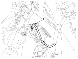
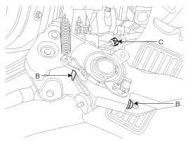
| 5. |
Remove the cable adjust nut (B) and cable guide (C). And then
detach the parking brake cable after tightening the fixing clip (D)
with cable tie.
|
| 6. |
Remove the floor console.
(Refer to Body - "Console") |
| 7. |
Remove the crash pad and cowl cross bar assembly.
(Refer to Body - "Crash Pad") |
| 8. |
Remove the heater & blower unit.
(Refer to Heating,Ventilation, Air Conditioning - "Heater Unit") |
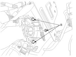
| 9. |
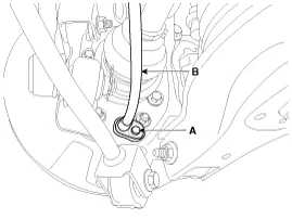
Loosen the cable fixing nut (B) and detach the rear parking
brake cable which is connected to the equalizer. And then remove front
parking brake cable (A).
|
Parking Brake Shoe
| 1. |
Raise the vehicle, and make sure it is securely supported. |
| 2. |
Remove the rear tire and wheel. |
| 3. |
Remove the brake caliper and Rear disc brake.
(Refer to "Rear Disc Brake Removal") |
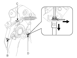
| 4. |
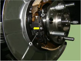
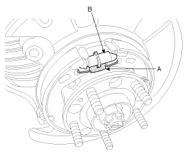
Remove the parking brake cable (B).
|
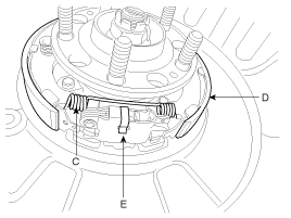
| 5. |
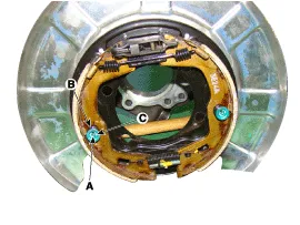
Remove the shoe hold down pin (A) and the spring (B), shoe
hold down washer (C) by pushing the retainer spring and turning the pin.
|
| 6. |
Remove the adjuster assembly (B), the lower return spring (A) and full off spring (C).
|
| 7. |
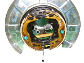
Remove the upper return spring (C) and the brake shoes (D).
|
| Installation |
Parking Brake Shoe
| 1. |
Install the operating lever assembly (E).
|
| 2. |
Install the upper return spring (C) and the brake shoes (D). |
| 3. |
Install the adjuster assembly (B) and the lower return spring (A).
|
| 4. |
While pressing the spring, install the brake shoe hold down pin (A) and spring (B).
|
| 5. |
Install the parking brake cable (B), then install the bolt (A).
|

| 6. |
Install the rear brake disc, then adjust the rear brake shoe clearance.
|
| 7. |
Install the brake caliper assembly.
(Refer to "Rear Brake Installation") |
| 8. |
Install the tire and wheel. |
| 9. |
If the parking brake shoe or the brake discare replaced with new ones, perform the brake shoe bed-in procedure.
|

Parking Brake Pedal
| 1. |
Install the parking brake cable (A).
|
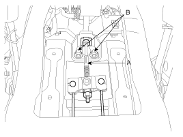
| 2. |
Install the fixing clip (C), washer plain (D) and cable adjusting nut (B) after fixing the parking brake cable.
|
| 3. |
Install the parking brake pedal, and then install the parking brake pedal mounting bolts and nut (D).
|
| 4. |
Adjust the parking brake pedal stroke by turning the adjusting nut(A).
|
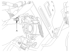
| 5. |
Reconnect the parking brake switch connector(A).
|
| 6. |
Install the heater & blower unit.
(Refer to Heating,Ventilation, Air Conditioning - "Heater Unit") |
| 7. |
Install the crash pad and cowl cross bar assembly.
(Refer to Body - "Crash Pad") |
| 8. |
Install the floor console.
(Refer to Body - "Console") |
| Adjustment |
Parking Brake Shoe Clearance Adjustment
| 1. |
Raise the vehicle, and make sure it is securely supported. |
| 2. |
Remove the rear tire and wheel. |
| 3. |
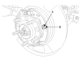
Remove the plug from the disc.
|
| 4. |
Rotate the toothed wheel of adjuster by a screw driver until
the disc does not move, and then return it by 6 notches in the opposite
direction. |
| 5. |
Install the plug on disc and then rear wheel & tire. |
Parking Brake Pedal Stroke Adjustment
| 1. |
Adjust the adjusting nut (A) so that parking brake pedal
strokeis to be 3 notches when operating effort is 196 N (20 kg.f, 44 lb)
after full stroke operation of parking brake pedal over 3 times for
setting parking wire.
|
Components 1. Parking brake pedal2. Front parking brake cable3. Equalizer assembly4. Rear parking brake cable Components Location 1. Backing plate2.
Description The EPB is an electronic parking brake. The EPB is different from existing parking systems which are operated with the brake pedal or the lever type.
Other information:
Hyundai Genesis (DH) 2013-2016 Service Manual: Head Up Display Unit Repair procedures
Removal 1. Disconnect the negative (-) battery terminal. 2. Remove the head up display bezel (A). 3. Remove the instrument cluster. (Refer to Indicators And Guages - "Instrument Cluster") 4. Remove the head up display unit bracket (A) after loosening the mounting nuts.
Hyundai Genesis (DH) 2013-2016 Service Manual: Components and Components Location
S
Categories
- Manuals Home
- Hyundai Genesis Owners Manual
- Hyundai Genesis Service Manual
- Description and Operation
- 4 Wheel Drive (AWD) System
- Heating, Ventilation and Air Conditioning
- New on site
- Most important about car

Copyright © 2026 www.hgenesisdh.com - 0.0282