Hyundai Genesis (DH): Intake And Exhaust System / Muffler Repair procedures
Hyundai Genesis (DH) 2013-2016 Service Manual / Engine Mechanical System / Intake And Exhaust System / Muffler Repair procedures
| Removal and Installation |
LH Front Muffler
| 1. |
Disconnect the battery "-" terminal from the trunk room. |
| 2. |
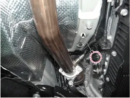
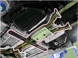
Disconnect the LH rear oxygen sensor connector (A).
|
| 3. |
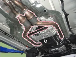
Remove the transmission stay bracket (A) and LH front muffler (B).
|
| 4. |
To install, reverse the removal procedure. |
RH Front Muffler
| 1. |
Disconnect the battery "-" terminal from the trunk room. |
| 2. |
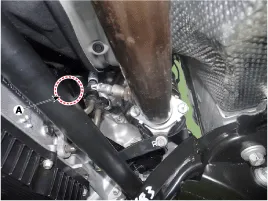
Disconnect the RH rear oxygen sensor connector (A).
|
| 3. |
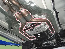
Remove the transmission stay bracket (A) and RH front muffler (B).
|
| 4. |
To install, reverse the removal procedure. |
Center Muffler
| 1. |
Disconnect the battery "-" terminal from the trunk room. |
| 2. |
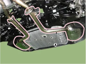
Remove the center muffler (A).
|
| 3. |
To install, reverse the removal procedure. |
LH Rear Muffler
| 1. |
Disconnect the battery "-" terminal from the trunk room. |
| 2. |
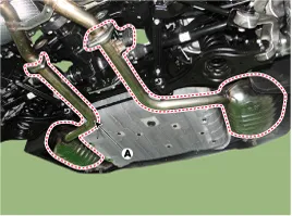
Remove the LH rear muffler (A).
|
| 3. |
To install, reverse the removal procedure. |
RH Rear Muffler
| 1. |
Disconnect the battery "-" terminal from the trunk room. |
| 2. |
Remove the RH rear muffler (A).
|
| 3. |
To install, reverse the removal procedure. |
Components 1. Front muffler2. Center muffler3. Rear muffler4. Hanger5. Gasket
Other information:
Hyundai Genesis (DH) 2013-2016 Service Manual: Auto Head Lamp Leveling Unit Repair procedures
Inspection 1. Ignition "ON". 2. Turn on the head lamp switch. 3. Check that the aim of the head lamp changes smoothly when the head lamp leveling device switch is turned on. 4. If it does not operate well, check the connector and terminals to make sure that they are connected.
Hyundai Genesis (DH) 2013-2016 Service Manual: Components and Components Location
C
Categories
- Manuals Home
- Hyundai Genesis Owners Manual
- Hyundai Genesis Service Manual
- Description and Operation
- Smart Cruise Control Unit Repair procedures
- Suspension System
- New on site
- Most important about car

Copyright © 2026 www.hgenesisdh.com - 0.0226