Hyundai Genesis (DH): Brake System / Front Disc Brake Repair procedures
| Removal |
| 1. |
Remove the front wheel & tire.
|
| 2. |
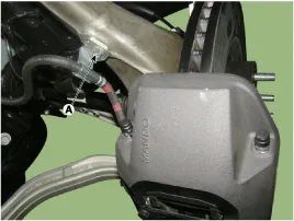
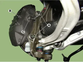
Remove the brake hose mounting bracket (A).
|
| 3. |
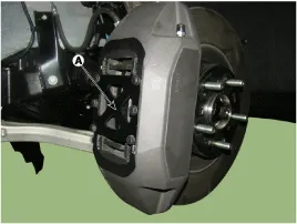
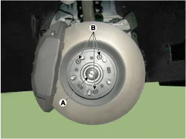
Remove the cover plate (A) by loosening the bolts.
|

| 4. |
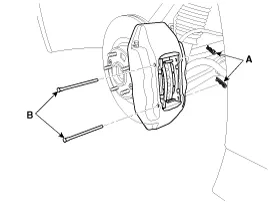
Remove locking pin (A) and guide pin (B).
|
| 5. |
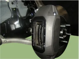
Remove the brake pad.
|
| 6. |
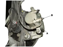
Loosen the hose eye-bolt (C) and caliper mounting bolts (A), then remove the front caliper assembly (B).
|
| 7. |
Loosen the coking nut (A) & screw (B) and then remove the disc.
|
| 1. |
Remove the front wheel & tire.
|
| 2. |
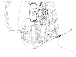
Loosen the guide rod bolt (B) and pivot the caliper up out of the way.
|
| 3. |
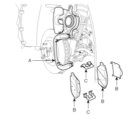
Remove pad shim (B), pad retainers (C) and brake pads (B) from the caliper bracket (A).
|
| 4. |
Loosen the hose eyebolt (B) and caliper mounting bolts (C), then remove the front caliper assembly (A).
|
| 5. |
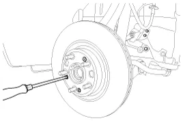
Remove the front brake disc by loosening the screws (3EA).
|
| Replacement |
| [4 Piston Type] |
| 1. |
Remove the cover plate (A) by loosening the bolts.
|
| 2. |
Remove locking pin (A) and guide pin (B).
|
| 3. |
Remove the brake pad.
|
| 1. |
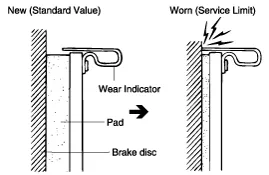
Check the brake pads for wear and fade. |
| 2. |
Check the brake disc for damage and cracks. |
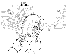
| 3. |
Remove all rust and contamination from the surface, and
measure the disc thickness at 8 points, at least, of same distance (5mm)
from the brake disc outer circle.
|
| 1. |
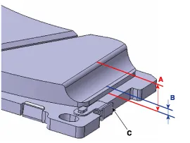
Check the pad wear. Measure the pad thickness and replace it, if it is less than the specified value.
|

| 1. |
Place a dial gauge about 5mm (0.2 in.) from the outer circumference of the brake disc, and measure the runout of the disc.
|
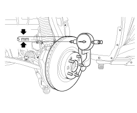
| 2. |
If the runout of the brake disc exceeds the limit
specification, reinstall the disc after turning the disc 72 |
Components 1. Caliper body2. Guide pin3. Locking pin4. Brake pad5. Cover plate 6. Pad spring7. Bleed screw
Components 1. Guide rod bolt2. Bleed screw3. Caliper body4. Caliper carrier5. Inner pad shim6. Brake pad7. Pad retainer
Other information:
Hyundai Genesis (DH) 2013-2016 Service Manual: Description and Operation
System Overview RPAS (Rear Parking Assist System) is an electronic driving aid that warns the driver to be cautious while parking or driving at low speed. The sensor uses ultrasonic waves to detect objects within proximity of the vehicle. RPAS consists of four RPS sensors which are detecting the obstacles and transmit the result separat
Hyundai Genesis (DH) 2013-2016 Service Manual: Description and Operation
Description Control Function This system supports 2 kinds of main function. (Rear video display function, Expected trace of wheels display function) The Rear video display and the expected trace of wheels display operate according to Vehicle speed condition and Gear position.
Categories
- Manuals Home
- Hyundai Genesis Owners Manual
- Hyundai Genesis Service Manual
- Repair procedures
- Steering System
- Emission Control System
- New on site
- Most important about car
