Hyundai Genesis (DH): Intake And Exhaust System / Exhaust Manifold Repair procedures
Hyundai Genesis (DH) 2013-2016 Service Manual / Engine Mechanical System / Intake And Exhaust System / Exhaust Manifold Repair procedures
| Removal and Installation |
LH Exhaust Manifold
| 1. |
Disconnect the battery "-" terminal from the trunk room. |
| 2. |
Loosen the drain plug and drain the engine coolant.
(Refer to Cooling System - "Coolant") |
| 3. |
Remove the water outlet pipe.
(Refer to Cooling System - "Water Temperature Control Assembly") |
| 4. |
Remove the LH front muffler.
(Refer to Intake And Exhaust System - "Muffler") |
| 5. |
Remove the engine oil level gauge and the pipe. |
| 6. |
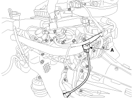
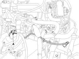
Disconnect the LH front oxygen sensor connector (A).
|
| 7. |
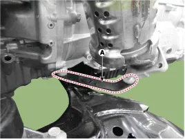
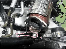
Remove the LH exhaust manifold stay (A).
|
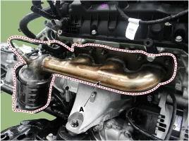
| 8. |
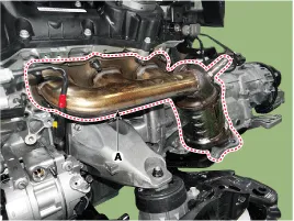
Remove the LH exhaust manifold assembly (A).
|
| 9. |
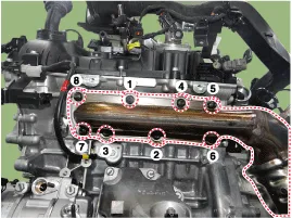
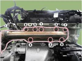
To install, reverse the removal procedure. |
When installing the exhaust manifold, tighten the nuts in the sequence shown below. |

RH Exhaust Manifold
| 1. |
Disconnect the battery "-" terminal from the trunk room. |
| 2. |
Loosen the drain plug and drain the engine coolant.
(Refer to Cooling System - "Coolant") |
| 3. |
Remove the air cleaner assembly.
(Refer to Intake And Exhaust System - "Air Cleaner") |
| 4. |
Remove the water inlet pipe.
(Refer to Cooling System - "Water Temperature Control Assembly") |
| 5. |
Remove the RH front muffler.
(Refer to Intake And Exhaust System - "Muffler") |
| 6. |
Disconnect the RH front oxygen sensor connector (A).
|
| 7. |
Remove the RH exhaust manifold stay (A).
|
| 8. |
Remove the RH exhaust manifold assembly (A).
|
| 9. |
To install, reverse the removal procedure. |
When installing the exhaust manifold, tighten the nuts in the sequence shown below. |
Components 1. LH Gasket2. LH Exhaust manifold3. RH Exhaust manifold stay4. RH Gasket5. RH Exhaust manifold6. RH Exhaust manifold stay
Components 1. Front muffler2. Center muffler3. Rear muffler4. Hanger5. Gasket
Other information:
Hyundai Genesis (DH) 2013-2016 Service Manual: Head Up Display Unit Repair procedures
Removal 1. Disconnect the negative (-) battery terminal. 2. Remove the head up display bezel (A). 3. Remove the instrument cluster. (Refer to Indicators And Guages - "Instrument Cluster") 4. Remove the head up display unit bracket (A) after loosening the mounting nuts.
Hyundai Genesis (DH) 2013-2016 Service Manual: In-car Sensor Repair procedures
I
Categories
- Manuals Home
- Hyundai Genesis Owners Manual
- Hyundai Genesis Service Manual
- Description and Operation
- Repair procedures
- 4 Wheel Drive (AWD) System
- New on site
- Most important about car

Copyright © 2026 www.hgenesisdh.com - 0.0255