Hyundai Genesis (DH): Engine Control System / Engine Coolant Temperature Sensor (ECTS) Description and Operation
Hyundai Genesis (DH) 2013-2016 Service Manual / Engine Control / Fuel System / Engine Control System / Engine Coolant Temperature Sensor (ECTS) Description and Operation
| Description |
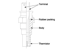
Engine Coolant Temperature Sensor (ECTS) is located in the
engine coolant passage of the cylinder head for detecting the engine
coolant temperature. The ECTS uses a thermistor whose resistance changes
with the temperature.
The electrical resistance of the ECTS decreases as the
temperature increases, and increases as the temperature decreases. The
reference +5V is supplied to the ECTS via a resistor in the ECM. That
is, the resistor in the ECM and the thermistor in the ECTS are connected
in series. When the resistance value of the thermistor in the ECTS
changes according to the engine coolant temperature, the output voltage
also changes.ion duration and controls the ignition timing using the
information of engine coolant temperature to avoid engine stalling and
improve drivability.
During cold engine operation, the ECM increases the fuel
injection duration and controls the ignition timing using the
information of engine coolant temperature to avoid engine stalling and
improve drivability.
Inspection 1. Connect the GDS on the Data Link Connector (DLC). 2. Measure the output voltage of the MAPS at idle and with ignition ON. ConditionOutput Voltage (V)IG ONApprox.
Specification TemperatureResistance (k?)
Other information:
Hyundai Genesis (DH) 2013-2016 Service Manual: Description and Operation
Description Control Function This system supports 2 kinds of main function. (Rear video display function, Expected trace of wheels display function) The Rear video display and the expected trace of wheels display operate according to Vehicle speed condition and Gear position.
Hyundai Genesis (DH) 2013-2016 Service Manual: Repair procedures
R
Categories
- Manuals Home
- Hyundai Genesis Owners Manual
- Hyundai Genesis Service Manual
- Engine Mechanical System
- 4 Wheel Drive (AWD) System
- Emission Control System
- New on site
- Most important about car

Copyright © 2026 www.hgenesisdh.com - 0.024