Hyundai Genesis (DH): Cruise Control System / Cruise Control Switch Repair procedures
Hyundai Genesis (DH) 2013-2016 Service Manual / Engine Electrical System / Cruise Control System / Cruise Control Switch Repair procedures
| Removal |
| 1. |
Turn the ignition switch OFF and disconnect the negative (-) battery cable. |
| 2. |
Remove the air-bag module from the steering wheel.
(Refer to Restraint - "Driver Airbag (DAB) Module and Clock Spring") |
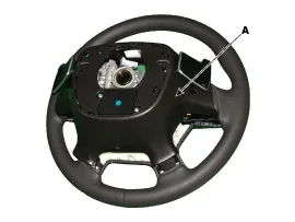
| 3. |
Remove the cover (A) after loosening the screw.
|
| 4. |
Disconnect the cruise control switch connector. |
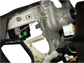
| 5. |
Remove the cruise control switch mounting screws (A).
|
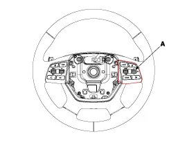
| 6. |
Remove the cruise control switch (A).
|
| Inspection |
| [Measuring Resistance] |
| 1. |
Disconnect the cruise control switch connector from the control switch.
|
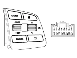
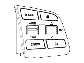
| 2. |
Measure resistance between terminals on the control switch when each function switch is ON (switch is depressed).
|
| 3. |
If not within specification, replace switch. |
| [Measuring Voltage] |
| 1. |
Connect the cruise control switch connector to the control switch.
|
| 2. |
Measure voltage between terminals on the harness side connector when each function switch is ON (switch is depressed).
|
| 3. |
If not within specification, inspect the control switch resistance.
The measuring resistance value is not within specification, replace the switch and measure the voltage again. |
| 4. |
If resistance is OK but, the measured voltage is not within
specification, inspect the wiring harness and connectors between the
switch and the ECM. |
| Installation |
| 1. |
Install in the reverse order of removal. |
Other information:
Hyundai Genesis (DH) 2013-2016 Service Manual: Auto Head Lamp Leveling Unit Description and Operation
Description According to driving environment and loading state of vehicle, head lamp lighting direction is changed to keep the driver's visibility range and to protect the driver's vision from glare, aiming at safety driving. Sensor integrated ECU mounting on the rear center arm drives the actuator mounting on the head lamp since sens
Hyundai Genesis (DH) 2013-2016 Service Manual: Auto Head Lamp Leveling Unit Repair procedures
Inspection 1. Ignition "ON". 2. Turn on the head lamp switch. 3. Check that the aim of the head lamp changes smoothly when the head lamp leveling device switch is turned on. 4. If it does not operate well, check the connector and terminals to make sure that they are connected.
Categories
- Manuals Home
- Hyundai Genesis Owners Manual
- Hyundai Genesis Service Manual
- General Information
- Steering System
- Description and Operation
- New on site
- Most important about car

Copyright © 2026 www.hgenesisdh.com - 0.0331