
Hyundai Genesis (DH): Cooling System / Cooling Fan Repair procedures
Hyundai Genesis (DH) 2013-2016 Service Manual / Engine Mechanical System / Cooling System / Cooling Fan Repair procedures
| Removal And Installation |
Cooling fan
| 1. |
Disconnect the battery "-" terminal from the trunk room. |
| 2. |
Remove the air cleaner assembly.
(Refer to Intake and Exhaust System - "Air Cleaner") |
| 3. |
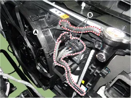
Disconnect the over flow hose (A) and cooling fan motor connector (B).
|
| 4. |
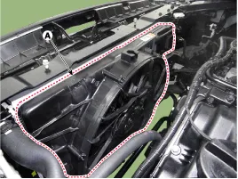
Loosen the cooling fan mounting bolts and then remove the cooling fan (A).
|
| 5. |
To install, reverse the removal procedure. |
Cooling fan controller (PWM)
| 1. |
Disconnect the battery "-" terminal from the trunk room. |
| 2. |
Remove the air cleaner assembly.
(Refer to Intake and Exhaust System - "Air Cleaner") |
| 3. |
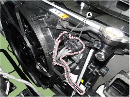
Disconnect the cooling fan motor connector (A).
|
| 4. |
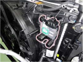
Remove the cooling fan controller (PWM) (A).
|
| 5. |
To install, reverse the removal procedure. |
| Disassembly |
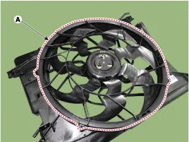
| 1. |
Remove the cooling fan rear cover (A).
|
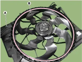
| 2. |
Remove the fan (B) from cooling fan assembly (A).
|
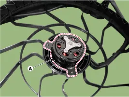
| 3. |
Remove the cooling fan motor (A).
|
| 4. |
To install, reverse the removal procedure. |
Cooling Circuit Diagram
Troubleshooting SymptomsRemedyIf the cooling fan is not functioning under normal operating conditions
Other information:
Hyundai Genesis (DH) 2013-2016 Service Manual: Auto Defogging Sensor Repair procedures
R
Hyundai Genesis (DH) 2013-2016 Service Manual: Temperature Control Actuator Repair procedures
Inspection 1. Turn the ignition switch OFF. 2. Disconnect the temperature control actuator connector. 3. Verify that the temperature control actuator operates to the warm (Driver's side) or cool (Passenger's side) position when connecting 12V to terminal 3 and grounding terminal 4.
Categories
- Manuals Home
- Hyundai Genesis Owners Manual
- Hyundai Genesis Service Manual
- Components and Components Location
- Brake System
- Starter Repair procedures
- New on site
- Most important about car

Copyright В© 2026 www.hgenesisdh.com - 0.0233