Hyundai Genesis (DH): Controller / Heater & A/C Control Unit Components and Components Location
Hyundai Genesis (DH) 2013-2016 Service Manual / Heating, Ventilation and Air Conditioning / Controller / Heater & A/C Control Unit Components and Components Location
| Component |
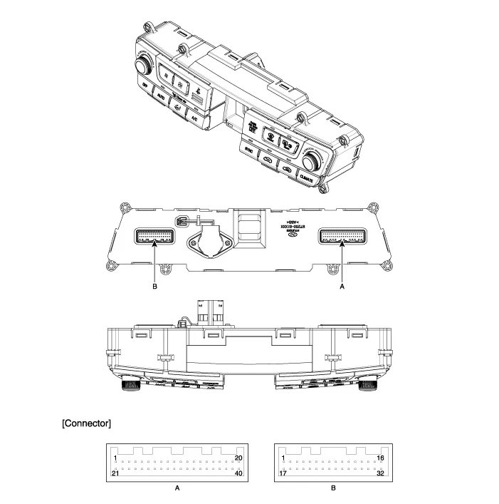
| Connector Pin Function |
| Pin No. | Connector A function | Pin No. | Connector B function |
| 1 | Taillight (ILL+) | 1 | Ground |
| 2 | Sensor REF(+5v) | 2 | Diagnosis ionizer |
| 3 | Driver's mode control actuator (Vent) | 3 | Clean signal |
| 4 | Driver's mode control actuator (Defrost) | 4 | - |
| 5 | Driver's mode control actuator feedback | 5 | Passenger's seat belt indicator |
| 6 | Driver's temperature control actuator (Cooling) | 6 | Rear seat belt indicator (Left) |
| 7 | Driver's temperature control actuator (Heating) | 7 | Rear seat belt indicator (Center) |
| 8 | Driver's temperature control actuator feedback | 8 | Rear seat belt indicator (Right) |
| 9 | Defrost actuator (Open) | 9 | Humidity sensor |
| 10 | Defrost actuator (Closed) | 10 | CO2 Sensor signal |
| 11 | Defrost actuator feedback | 11 | - |
| 12 | Intake actuator (FRE) | 12 | Evaporator sensors(+) |
| 13 | Intake actuator(REF) | 13 | Rear defogging sensor |
| 14 | Intake actuator feedback | 14 | Heat |
| 15 | - | 15 | Idle Stop&Go-DC |
| 16 | - | 16 | Battery |
| 17 | - | 17 | Sensor ground |
| 18 | - | 18 | Console mode actuator (Rear seat vent) |
| 19 | K-LINE | 19 | Console mode actuator (Rear seat floor) |
| 20 | Leo stat (ILL-) | 20 | Console mode actuator feedback |
| 21 | Ignition 2 | 21 | Console temperature actuator (Cooling) |
| 22 | Mode actuator (Vent) | 22 | Console temperature actuator (Heating) |
| 23 | Mode actuator (Defrost) | 23 | Console temperature actuator feedback |
| 24 | Mode actuator feedback | 24 | Console On/Off actuator (Off) |
| 25 | Driver's temperature actuator (Cooling) | 25 | Console On/Off actuator (On) |
| 26 | Driver's temperature actuator (Heating) | 26 | Console On/Off actuator feedback |
| 27 | Temperature actuator feedback | 27 | Console temperature switch actuator |
| 28 | P-CAN(HIGH) | 28 | Console On/Off actuator (On) |
| 29 | P-CAN(LOW) | 29 | PAB ON Sine |
| 30 | DETENT OUT | 30 | PAB OFF Sine |
| 31 | - | 31 | PAB lgnition |
| 32 | PTC Signal ON | 32 | lgnition 1 |
| 33 | PTC Relay 2 | ? | ? |
| 34 | PTC Relay 3 | ? | ? |
| 35 | ECV + | ? | ? |
| 36 | ECV- (Ground) | ? | ? |
| 37 | Blower motor (+) | ? | ? |
| 38 | FET (Gate) | ? | ? |
| 39 | FET (Drain feedback) | ? | ? |
| 40 | Ground | ? | ? |
Self Diagnosis 1. Self-diagnosis process 2. How to read self-diagnostic code After the display panel blinks three times every 0.5 second, the corresponding fault code blinks on the setup temperature display panel every 0.
Other information:
Hyundai Genesis (DH) 2013-2016 Service Manual: Description and Operation
Description BSD is a system that measures the speed of and distance from the following vehicles by using two magnetic wave radar sensors attached to the rear bumper, and detects any vehicle within the blind spot zone and gives off alarm (visual and auditory).
Hyundai Genesis (DH) 2013-2016 Service Manual: Blind Spot Detection Indicator Repair procedures
Removal Blind Spot Detection Warning Indicator 1. Disconnect the negative (-) battery terminal. 2. Remove the mirror (A). Installation Blind Spot Detection Warning Indicator 1. Install the outside mirror. 2. Connect the negative (-) battery terminal.
Categories
- Manuals Home
- Hyundai Genesis Owners Manual
- Hyundai Genesis Service Manual
- Smart Cruise Control Unit Repair procedures
- Emission Control System
- Body (Interior and Exterior)
- New on site
- Most important about car

Copyright © 2026 www.hgenesisdh.com - 0.0252