Hyundai Genesis (DH): Engine Control System / Fuel Tank Pressure Sensor (FTPS) Description and Operation
Hyundai Genesis (DH) 2013-2016 Service Manual / Engine Control / Fuel System / Engine Control System / Fuel Tank Pressure Sensor (FTPS) Description and Operation
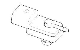
| Description |
Fuel Tank Pressure Sensor (FTPS) is a component of the
evaporative emission control system and is installed on the fuel tank,
the fuel pump, or the canister. It checks the purge control solenoid
valve operation and detects a leakage of the system.
Inspection 1. Connect the GDS on the Data Link Connector (DLC). 2. Turn the ignition switch ON. 3. Measure the output voltage of the APS 1 and 2 at C.
Specifications Pressure [kPa (kgf/cm?, in H2O)Output Voltage (V)'-6.67 (-0.068, -26.8)0.502.5'+6.67 (0.068, 26.8)4.5
Other information:
Hyundai Genesis (DH) 2013-2016 Service Manual: Components and Components Location
C
Hyundai Genesis (DH) 2013-2016 Service Manual: Climate Control Air Filter Repair procedures
Replacement 1. Remove both stoppers (B) by turning them from the glove box (A). 2. Disconnect the air damper (A) from the glove box (B). 3. Remove the filter cover (A) by pressing the knob. 4. Replace the air filter (A) with a new one according to the direction of air filter.
Categories
- Manuals Home
- Hyundai Genesis Owners Manual
- Hyundai Genesis Service Manual
- Emission Control System
- Active Air Flap(AAF) Repair procedures
- Body (Interior and Exterior)
- New on site
- Most important about car

Copyright © 2026 www.hgenesisdh.com - 0.0266