Hyundai Genesis (DH): Fuel Delivery System / Fuel Line Repair procedures
| Removal |
| 1. |
Turn the ignition switch OFF and disconnect the negative (-) battery terminal. |
| 2. |
Release the residual pressure in fuel line.
(Refer to Fuel Delivery System - "Release Residual Pressure in Fuel Line") |
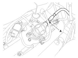
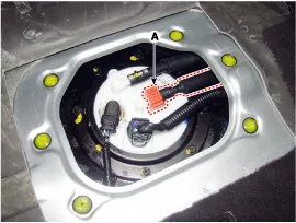
| 3. |
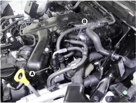
Disconnect the fuel feed tube quick-connector (A). |
| 4. |
Disconnect the vapor hose (B) which is connected to the PCSV.
|
| 5. |
Remove the front-LH wheel, tire and the inner wheel house. |
| 6. |
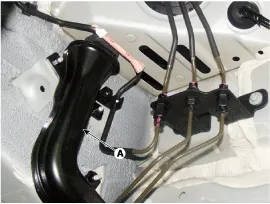
Remove the fuel line protector (A) after removing mounting nuts.
|
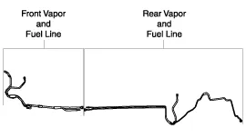
| 7. |
Disconnect the front vapor and fuel tube line quick-connector (A).
|
| 8. |
Remove the noise barrier (A) after loosening the mounting bolt and nut. |
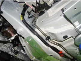
| 9. |
Remove the front vapor and fuel tube line (B).
|
| 10. |
Remove the fuel tank.
(Refer to Fuel Delivery System - "Fuel Tank") |
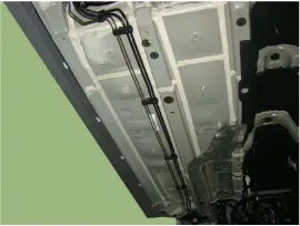
| 11. |
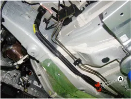
Remove the vapor tube and fuel feed tube line fixing clips (A) by using a common driver.
|
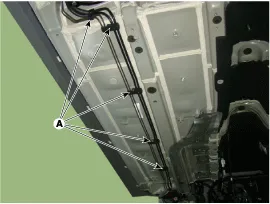
| 12. |
Remove the fuel line from the bottom of the vehicle.
|
| Installation |
| 1. |
To install, reverse the removal procedure.
|
| Inspection |
| 1. |
Start the engine. |
| 2. |
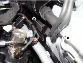
Check the fuel feed line (A) installation state and fuel leakage state.
|
| 3. |
Fold the rear seat cushion. |
| 4. |
Remove the fuel pump service cover (A) after loosening the screws.
|
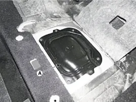
| 5. |
Check the fuel feed quick-connector (A) installation state and fuel leakage state.
|
| 6. |
Lift the vehicle. |
| 7. |
Check the fuel leakage state.
|
| 8. |
Replace the fuel line after checking the abnormal fuel line.
(Refer to Fuel Delivery System - "Fuel Line") |
Inspection 1. Connect the GDS on the Data Link Connector (DLC). 2. Check the output voltage of fuel pressure sensor (FPS). Specification: Refer to
Removal 1. Remove the filler neck mounting screws (A) after opening the fuel filler door. 2. Remove the rear-left wheel & tire and wheel house cover.
Other information:
Hyundai Genesis (DH) 2013-2016 Service Manual: High Mounted Stop Lamp Repair procedures
Removal High Mounted Stop Lamp 1. Disconnect the negative (-) battery terminal. 2. Remove the roof trim assembly. (Refer to Body - "Roof Trim") 3. Remove the high mounted stop lamp assembly (A) after loosening the mounting screws. Installation 1.
Hyundai Genesis (DH) 2013-2016 Service Manual: Compressor Description and Operation
Description The compressor is the power unit of the A/C system. It is located on the side of engine block and driven by a V-belt of the engine. The compressor changes low-pressure and low-temperature refrigerant gas into high-pressure and high-temperature refrigerant gas.
Categories
- Manuals Home
- Hyundai Genesis Owners Manual
- Hyundai Genesis Service Manual
- Body Electrical System
- General Information
- Body (Interior and Exterior)
- New on site
- Most important about car
