Hyundai Genesis (DH): AVN System / Front LCD monitor Repair procedures
Hyundai Genesis (DH) 2013-2016 Service Manual / Body Electrical System / AVN System / Front LCD monitor Repair procedures
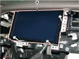
| Removal |
Take care not to scratch the crash pad and related parts. |

| 1. |
Disconnect the negative (-) battery terminal. |
| 2. |
Remove the crash pad side garnish assembly.
(Refer to Body - "Crash pad side garnish assembly")
|
| 3. |
Remove the fascia panel monitor.
(Refer to Body - "Crash Pad Main Lower Assembly") |
| 4. |
Remove the front LCD monitor after loosening the mounting screws.
|
| Installation |
| 1. |
Install the front LCD monitor after connecting the connector. |
| 2. |
Install the monitor fascia panel.
|
Components NO.Connector ANO.Connector BNO.Connector C1B (+)1-1Right side low (+)2B (+)2-2Left side low (+)3B (+)3-3Right front midrange/tweeter (+)4-4-4Left front midrange/tweeter (+)5Multimedia-CAN (high)5-5Right front door (+)6Multimedia-CAN (low)6-6Left front door (+)7ACC7-7Right side low (-)8-8-8Left side low (-)9-9-9Right front midrange/tweeter (-)10-10-10Left front midrange/tweeter (-)11NAVI sound (+)11-11Right front door (-)12Sub woofer 2 (+)12-12Left front door (-)13Sub woofer 1 (+)13-1314GND14-1415GND15-1516GND16-1617-171718SPDIF (+)181819SPDIF (-)191920SPDIF GND(shield)202021-212122-222223-2324NAVI sound (-)2425Sub woofer 2 (-)2526Sub woofer 1 (-)26
Categories
- Manuals Home
- Hyundai Genesis Owners Manual
- Hyundai Genesis Service Manual
- Starter Repair procedures
- Electric Parking Brake (EPB) Repair procedures
- 4 Wheel Drive (AWD) System
- New on site
- Most important about car

Copyright © 2026 www.hgenesisdh.com - 0.0298