Hyundai Genesis (DH): Brake System / Front Disc Brake Repair procedures
Hyundai Genesis (DH) 2013-2016 Service Manual / Brake System / Brake System / Front Disc Brake Repair procedures
| Removal |
[4 Piston Type]
| 1. |
Remove the front wheel & tire.
|
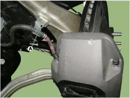
| 2. |
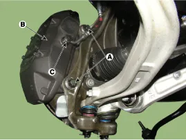
Remove the brake hose mounting bracket (A).
|
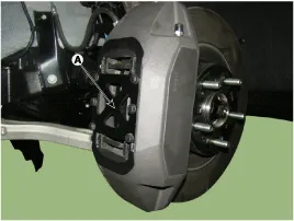
| 3. |
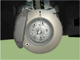
Remove the cover plate (A) by loosening the bolts.
|

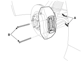
| 4. |
Remove locking pin (A) and guide pin (B).
|
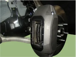
| 5. |
Remove the brake pad.
|
| 6. |
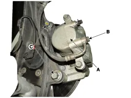
Loosen the hose eye-bolt (C) and caliper mounting bolts (A), then remove the front caliper assembly (B).
|
| 7. |
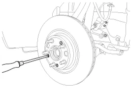
Loosen the coking nut (A) & screw (B) and then remove the disc.
|
[Single Piston Type]
| 1. |
Remove the front wheel & tire.
|
| 2. |
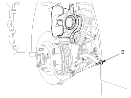
Loosen the guide rod bolt (B) and pivot the caliper up out of the way.
|
| 3. |
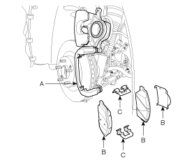
Remove pad shim (B), pad retainers (C) and brake pads (B) from the caliper bracket (A).
|
| 4. |
Loosen the hose eyebolt (B) and caliper mounting bolts (C), then remove the front caliper assembly (A).
|
| 5. |
Remove the front brake disc by loosening the screws (3EA).
|
| Replacement |
Brake pad
| [4 Piston Type] |
| 1. |
Remove the cover plate (A) by loosening the bolts.
|
| 2. |
Remove locking pin (A) and guide pin (B).
|
| 3. |
Remove the brake pad.
|
Front Brake Disc Thickness Check
| 1. |
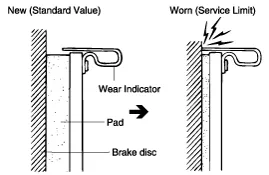
Check the brake pads for wear and fade. |
| 2. |
Check the brake disc for damage and cracks. |
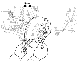
| 3. |
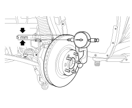
Remove all rust and contamination from the surface, and
measure the disc thickness at 8 points, at least, of same distance (5mm)
from the brake disc outer circle.
|
Front Brake Pad Check
| 1. |
Check the pad wear. Measure the pad thickness and replace it, if it is less than the specified value.
|

Front Brake Disc Runout Check
| 1. |
Place a dial gauge about 5mm (0.2 in.) from the outer circumference of the brake disc, and measure the runout of the disc.
|
| 2. |
If the runout of the brake disc exceeds the limit
specification, reinstall the disc after turning the disc 72 |
Components 1. Caliper body2. Guide pin3. Locking pin4. Brake pad5. Cover plate 6. Pad spring7. Bleed screw
Components 1. Guide rod bolt2. Bleed screw3. Caliper body4. Caliper carrier5. Inner pad shim6. Brake pad7. Pad retainer
Other information:
Hyundai Genesis (DH) 2013-2016 Service Manual: Components and Components Location
S
Hyundai Genesis (DH) 2013-2016 Service Manual: CO2 Sensor Description and Operation
Description This system maintains the density of carbon dioxide constantly in vehicle interior by measuring the amount of carbon dioxide to increase the comfortableness and the fuel consumption rate when air conditioning system is operating.
Categories
- Manuals Home
- Hyundai Genesis Owners Manual
- Hyundai Genesis Service Manual
- Components and Components Location
- Restraint
- Starter Repair procedures
- New on site
- Most important about car

Copyright © 2026 www.hgenesisdh.com - 0.0226