
Hyundai Genesis (DH): Engine And Transaxle Assembly / Engine Room Under Cover Repair procedures
| Removal and Installation |
| 1. |
Remove the front under cover (A). Remove the rear under cover(B).
|

| 2. |
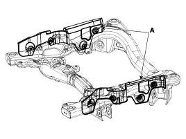
Remove the RH/LH side cover (A).
|
| 3. |
To install, reverse the removal procedure. |
Components [2WD] 1. Front under cover2. Rear under cover3. LH side cover4. RH side cover [AWD] 1. Front under cover2. Rear under cover3.
Components [2WD] 1. Engine mounting insulator assembly2. Engine support bracket LH3. Engine support bracket RH4. Transmission mounting insulator [AWD] 1.
Other information:
Hyundai Genesis (DH) 2013-2016 Service Manual: Parking Assist Sensor Repair procedures
Removal 1. Disconnect the negative (-) battery terminal. 2. Remove the front/rear bumper cover. (Refer to Body - "Front Bumper Cover") (Refer to Body - "Rear Bumper Cover") 3. Disconnect the connector (B) from the parking assist sensor (A).
Hyundai Genesis (DH) 2013-2016 Service Manual: PGS Unit (Back & Blinde Unit) Repair procedures
Removal 1. Disconnect the negative (-) battery terminal. 2. Remove the glove box housing (A). (Refer to Body - "Glove Box") 3. Remove the PGS unit (A) after loosening the nuts. Installation 1. Install the PGS unit. 2. Install the glove box housing.
Categories
- Manuals Home
- Hyundai Genesis Owners Manual
- Hyundai Genesis Service Manual
- Body Electrical System
- Suspension System
- Engine Electrical System
- New on site
- Most important about car
