Hyundai Genesis: Cylinder Head Assembly / Cylinder Head Cover Repair procedures

Removal
LH Cylinder Head Cover
1.
Disconnect the battery "-" terminal from the trunk room.
2.
Remove the surge tank.
(Refer to Intake And Exhaust System - "Surge Tank")
3.
Remove the intake manifold.
(Refer to Intake And Exhaust System - "Intake Manifold")
4.
Remove the high-pressure fuel pipe.
(Refer to Fuel system - "delivery pipe")
5.
Remove the LH ignition coil and wiring.
(Refer to Engine Electrical System - "Ignition Coil")
6.
Remove the high pressure fuel pump.
(Refer to Engine Control / Fuel System - "High Pressure Fuel Pump")
7.
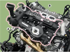
Remove the LH cylinder head cover.
(1)
Remove the LH exhaust CVVT oil control valve (OCV) cap (A).
(2)
Remove the LH cylinder head cover (B).

   
Cover the cylinder head with a piece of clean cloth or vinyl cover to prevent foreign materials from entering the cylinder head.
RH Cylinder Head Cover
1.
Disconnect the battery "-" terminal from the trunk room.
2.
Remove the surge tank.
(Refer to Intake And Exhaust System - "Surge Tank")
3.
Remove the RH ignition coil and wiring.
(Refer to Engine Electrical System - "Ignition Coil")
4.
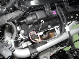
Remove the RH exhaust CMP sensor connector (A).

5.
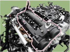
Remove the RH cylinder head cover.
(1)
Remove the RH exhaust CVVT oil control valve (OCV) cap (A).
(2)
Remove the RH cylinder head cover (B).

   
Cover the cylinder head with a piece of clean cloth or vinyl cover to prevent foreign materials from entering the cylinder head.
Installation
LH Cylinder Head Cover
1.
Install the LH cylinder head cover.
   
Install the cylinder head cover under the exhaust oil control valve (OCV) cap
To prevent engine oil leakage, surely install the exhaust OCV cap after installing the cylinder head cover.
(1)
The hardening sealant located on the upper area between timing chain cover and cylinder head should be removed before assembling cylinder head cover.
(2)
After applying THREE BOND 1217H sealant, it should be assembled within 5 minutes.

Bead width : 2.5 mm (0.1 in.)

(3)
The firing and/or blow out test should not be performed within 30 minutes after the cylinder head cover was assembled.
(4)
Install the cylinder head cover bolts as following method.

Tightening torque
1st step :
4.9 ~ 5.9 N.m (0.5 ~ 0.6 kgf.m, 3.6 ~ 4.3 lb-ft)
2nd step :
9.8 ~ 11.8 N.m (1.0 ~ 1.2 kgf.m, 7.2 ~ 8.7 lb-ft)

   
Do not reuse a cylinder head cover gasket.
(5)
Install the LH exhaust CVVT oil control valve cap.

Tightening torque :
9.8 ~ 11.8 N.m (1.0 ~ 1.2 kgf.m, 7.2 ~ 8.7 lb-ft)

   
Always use a new exhaust CVVT oil control valve cap.
2.
To install the other parts, reverse the removal procedure.
RH Cylinder Head Cover
1.
Install the RH cylinder head cover.
   
Install the cylinder head cover under the exhaust oil control valve (OCV) cap
To prevent engine oil leakage, surely install the exhaust OCV cap after installing the cylinder head cover.
(1)
The hardening sealant located on the upper area between timing chain cover and cylinder head should be removed before assembling cylinder head cover.
(2)
After applying THREE BOND 1217H sealant, it should be assembled within 5 minutes.

Bead width : 2.5 mm (0.1 in.)

(3)
The firing and/or blow out test should not be performed within 30 minutes after the cylinder head cover is assembled.
(4)
Install the RH cylinder head cover bolts as following method.

Tightening torque
1st step :
4.9 ~ 5.9 N.m (0.5 ~ 0.6 kgf.m, 3.6 ~ 4.3 lb-ft)
2nd step :
9.8 ~ 11.8 N.m (1.0 ~ 1.2 kgf.m, 7.2 ~ 8.7 lb-ft)

   
Do not reuse the cylinder head cover gasket.
(5)
Install the RH exhaust CVVT oil control valve cap.

Tightening torque :
9.8 ~ 11.8 N.m (1.0 ~ 1.2 kgf.m, 7.2 ~ 8.7 lb-ft)

   
Always use a new exhaust CVVT oil control valve cap.
2.
To install the other parts, reverse the removal procedure.
Cylinder Head Cover Components and Components Location
Components 1. LH cylinder head cover2. LH cylinder head cover gasket3. LH exhaust CVVT OCV cap4. RH cylinder head cover5. RH cylinder head cover gasket6. RH exhaust CVVT OCV cap ...

CVVT Assembly Components and Components Location
Components 1. RH exhaust CVVT2. RH intake CVVT3. LH intake CVVT4. LH exhaust CVVT ...

Other information:

Hyundai Genesis (DH) 2013-2016 Service Manual: Relay Box (Engine Compartment) Repair procedures


Inspection 1. Disconnect the negative (-) battery terminal. 2. Pull out the relay from the engine compartment relay box. Power Relay (Type A) Check for continuity between the terminals. A : start relay 1. After supplying power to between No. 85 and 86 power relay terminals, check t ...

Hyundai Genesis (DH) 2013-2016 Owners Manual: Warning messages


Parking brake automatically locked When the EPB is applied from Auto Hold, a warning will sound and a message will appear. AUTO HOLD deactivating. Press brake pedal When the conversion from Auto Hold to EPB is not working properly a warning will sound and a message will appear. C ...

© 2013-2024 www.hgenesisdh.com