
Hyundai Genesis (DH): BCM (Body Control Module) / Components and Components Location
Hyundai Genesis (DH) 2013-2016 Service Manual / Body Electrical System / BCM (Body Control Module) / Components and Components Location
| Components |
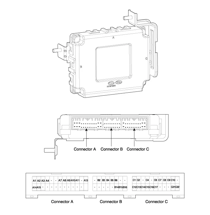
| NO | Connector A | Connector B | Connector C |
| 1 | Battery + | - | Room lamp Output |
| 2 | IGN1 | ECM Mirror + | Foot lamp Output |
| 3 | IGN2 | B CAN High | - |
| 4 | ACC | B CAN Low | - |
| 5 | - | PAS (LIN) | - |
| 6 | - | Integrated sensor (LIN) | L_Head lamp washer RLY_OUT |
| 7 | Rear Window Defroster switch | - | External buzzer output |
| 8 | parking brake switch | - | SSB light output |
| 9 | PAS off switch | - | Mood lamp output |
| 10 | Rear curtain switch | - | Rear curtain motor down Output |
| 11 | sunroof state | - | Rear curtain motor UP Output |
| 12 | - | - | ATM Solenoid outputs |
| 13 | Trunk open switch | - | Rear Seat belt light output(RH) |
| 14 | L_NADRI_OPT_IN | Rear Seat belt light output(LH) | Rear defogger light output |
| 15 | L_Deolicated DRI_OPT_IN | Rear Seat belt light output(Center) | PAS on light output |
| 16 | - | GND (Power) | safety belt light output (Assist) |
| 17 | - | ? | security light output |
| 18 | - | ? | - |
| 19 | - | ? | - |
| 20 | - | ? | - |
| 21 | - | ? | GND (Rear curtain motor) |
| 22 | - | ? | Rear curtain Power |
| 23 | - | ? | ? |
| 24 | - | ? | ? |
| 25 | - | ? | ? |
| 26 | GND | ? | ? |
Specifications ItemsSpecificationsRated voltageDC 12VOperating voltageDC 9 ~ 16VOperating temperature-30
Circuit Diagram
Categories
- Manuals Home
- Hyundai Genesis Owners Manual
- Hyundai Genesis Service Manual
- Description and Operation
- Description and Operation
- Description and Operation
- New on site
- Most important about car

Copyright В© 2026 www.hgenesisdh.com - 0.0234