Hyundai Genesis (DH): Tire Pressure Monitoring System / TPMS Receiver Repair procedures
Hyundai Genesis (DH) 2013-2016 Service Manual / Suspension System / Tire Pressure Monitoring System / TPMS Receiver Repair procedures
| Replacement |
| 1. |
Disconnect the negative (-) battery cable. |
| 2. |
Remove the crash pad.
(Refer to Body - "Crash Pad") |
| 3. |
Remove the connector. |
| 4. |
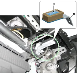
Remove the bracket (B) and receiver (C) by loosening the nut (A).
|
| 5. |
Install in the reverse order of removal. |
| 6. |
Re-connect the battery, and then turn on the ignition.
|

| 7. |
Replace the receiver, and then perform the learning process using a diagnostic instrument (GDS). |
| Diagnostic Procedure Using a Diagnostic Instrument |
The following section describes how to diagnose faults using a diagnostic instrument.
| 1. |
Connect the diagnostic instrument to the self-diagnostic
connector (16-pin) beneath the crash pad on the side of driver's seat,
and then turn on the ignition to activate the diagnostic instrument. |
| 2. |
In the GDS Vehicle Type Selection menu, select "Vehicle Type" and "TPMS" System, and then opt for "OK." |
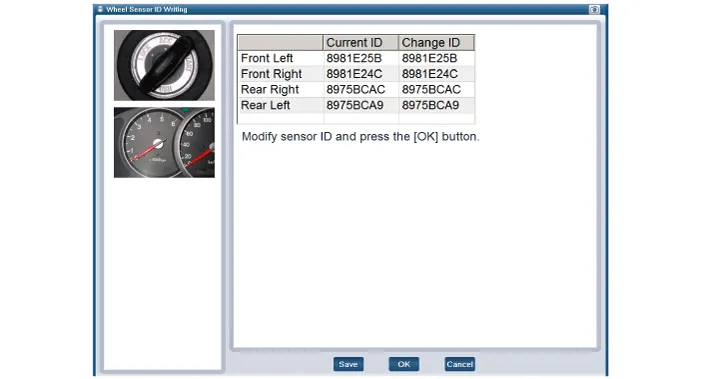
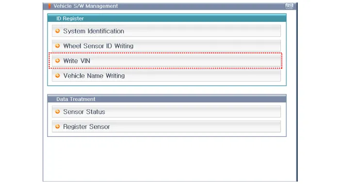
[Wheel Sensor ID Writing (Wireless)]
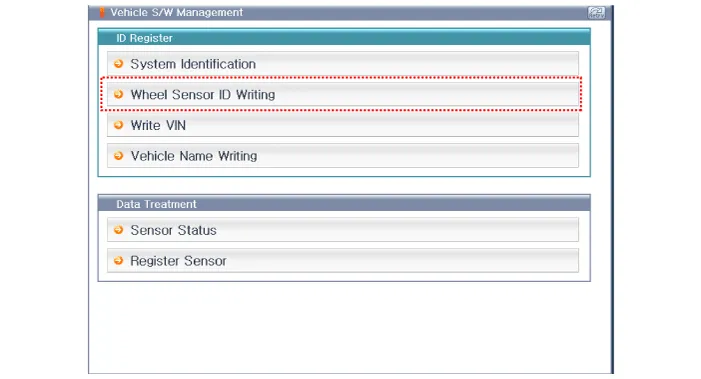
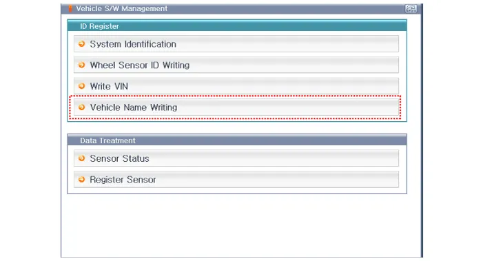
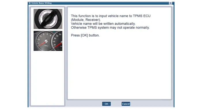
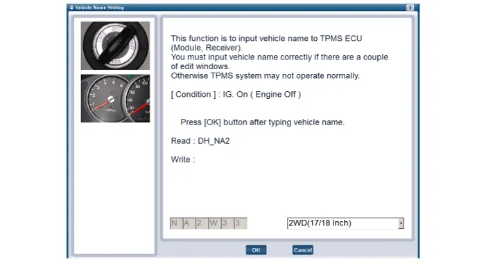
[Vehicle Name Writing]
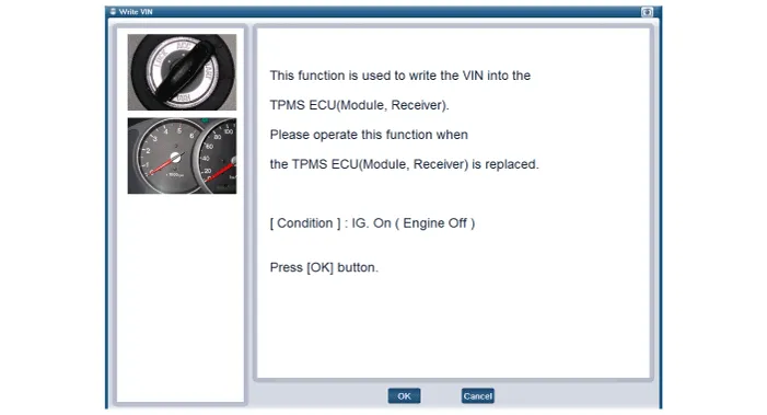
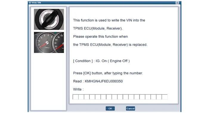
[VIN Writing]
Circuit Diagram 1. Circuit diagram 2. Receiver connector terminals. 3. Receiver connector function. No FunctionDescription1BatteryVBAT2IG ONBattery to IG ON3CAN_HighCAN_High4CAN_LowCAN_Low5GroundBattery to ground6--
Other information:
Hyundai Genesis (DH) 2013-2016 Service Manual: Parking Assist Sensor Repair procedures
Removal 1. Disconnect the negative (-) battery terminal. 2. Remove the front/rear bumper cover. (Refer to Body - "Front Bumper Cover") (Refer to Body - "Rear Bumper Cover") 3. Disconnect the connector (B) from the parking assist sensor (A).
Hyundai Genesis (DH) 2013-2016 Service Manual: Compressor Repair procedures
Removal 1. If the compressor is marginally operable, run the engine at idle speed, and let the air conditioning work for a few minutes, then shut the engine off. 2. Disconnect the negative (-) battery terminal. 3. Remove the engine room cover.
Categories
- Manuals Home
- Hyundai Genesis Owners Manual
- Hyundai Genesis Service Manual
- Starter Repair procedures
- Transmission Control Module (TCM) Repair procedures
- Active Air Flap(AAF) Repair procedures
- New on site
- Most important about car

Copyright © 2026 www.hgenesisdh.com - 0.0423