Hyundai Genesis (DH): Starting System / Starter Repair procedures
| Removal |
| 1. |
Turn ignition switch OFF and disconnect the negative (-) battery cable. |
| 2. |
Remove the RH engine manifold.
(Refer to Engine Mechanical System - "Exhaust Manifold") |
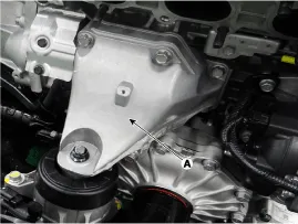
| 3. |
Remove the engine support bracket (A) after loosening the install bolt and nut.
|
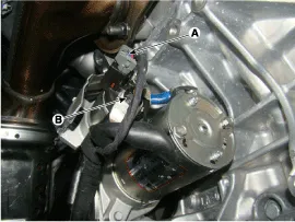
| 4. |
Disconnect the starter connector (A) and cable (B) from the 'B' terminal.
|
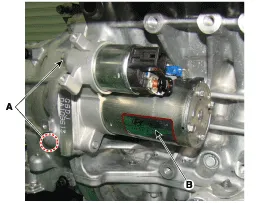
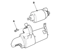
| 5. |
Remove the starter (B) after removing the mounting bolts (A).
|
| Installation |
| 1. |
Install in the reverse order of removal.
|
| Disassembly |
| 1. |
Disconnect the M-terminal from the magnet switch assembly.
|
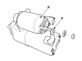
| 2. |
After loosening the 3 screws (A), detach the magnet switch assembly (B).
|
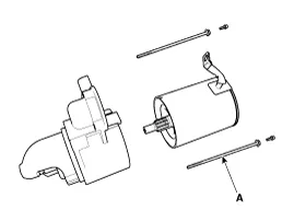
| 3. |
Loosen the through bolts (A).
|
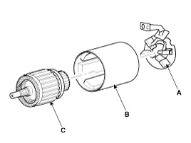
| 4. |
Remove the brush holder assembly (A), yoke (B) and armature (C).
|
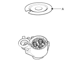
| 5. |
Remove the shield (A).
|
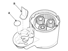
| 6. |
Remove the lever plate (A) and lever packing (B).
|
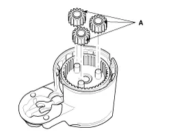
| 7. |
Disconnect the planet gear (A).
|
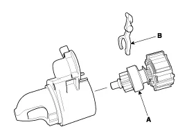
| 8. |
Disconnect the planet shaft assembly (A) and lever (B).
|
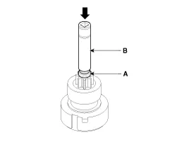
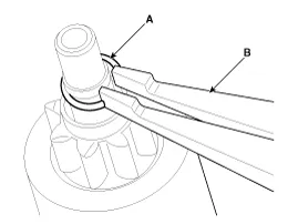
| 9. |
Press the stop ring (A) using a socket (B).
|
| 10. |
Remove the stopper (A) using the stopper pliers (B).
|
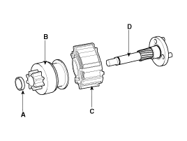
| 11. |
Disconnect the stop ring (A), overrunning clutch (B), internal gear (C) and planet shaft (D).
|
| 12. |
To reassemble, reverse the order of disassembly.
|

| Inspection |
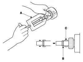
| 1. |
Disconnect the lead wire from the M-terminal of solenoid switch. |
| 2. |
Connect the battery as shown. If the starter pinion pops out, it is working properly.
|
