Hyundai Genesis (DH): Starting System / Starter Relay Repair procedures
| Inspection |
| 1. |
Turn ignition switch OFF and disconnect the negative (-) battery cable. |
| 2. |
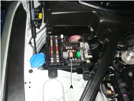
Remove the fuse box cover. |
| 3. |
Remove the starter relay (A).
|
| 4. |
Using an ohmmeter, check that there is continuity between each terminal.
|
| 5. |
Apply 12V to between terminals 85 and 86, and then check for continuity between terminals 30 and 87.
|
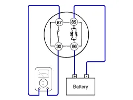
| 6. |
If there is no continuity, replace the starter relay. |
| 7. |
Install the starter relay. |
| 8. |
Install the fuse box cover. |
Removal 1. Turn ignition switch OFF and disconnect the negative (-) battery cable. 2. Remove the RH engine manifold. (Refer to Engine Mechanical System - "Exhaust Manifold") 3.
Other information:
Hyundai Genesis (DH) 2013-2016 Service Manual: General Safety Information and Caution
Instructions When Handling Refrigerant 1. R-134a liquid refrigerant is highly volatile. A drop on the skin of your hand could result in localized frostbite. When handling the refrigerant, be sure to wear gloves. 2. It is standard practice to wear goggles or glasses to protect your eyes, and gloves to protect your hands.
Hyundai Genesis (DH) 2013-2016 Service Manual: Compressor oil Repair procedures
Oil Specification 1. The HFC-134a system requires synthetic (PAG) compressor oil whereas the R-12 system requires mineral compressor oil. The two oils must never be mixed. 2. Compressor (PAG) oil varies according to compressor model. Be sure to use oil specified for the compressor model.
Categories
- Manuals Home
- Hyundai Genesis Owners Manual
- Hyundai Genesis Service Manual
- General Information
- Engine Mechanical System
- Brake System
- New on site
- Most important about car
