Hyundai Genesis (DH): Starting System / Starter Relay Repair procedures
Hyundai Genesis (DH) 2013-2016 Service Manual / Engine Electrical System / Starting System / Starter Relay Repair procedures
| Inspection |
| 1. |
Turn ignition switch OFF and disconnect the negative (-) battery cable. |
| 2. |
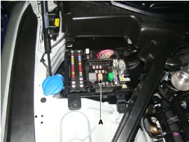
Remove the fuse box cover. |
| 3. |
Remove the starter relay (A).
|
| 4. |
Using an ohmmeter, check that there is continuity between each terminal.
|
| 5. |
Apply 12V to between terminals 85 and 86, and then check for continuity between terminals 30 and 87.
|
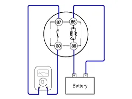
| 6. |
If there is no continuity, replace the starter relay. |
| 7. |
Install the starter relay. |
| 8. |
Install the fuse box cover. |
Removal 1. Turn ignition switch OFF and disconnect the negative (-) battery cable. 2. Remove the RH engine manifold. (Refer to Engine Mechanical System - "Exhaust Manifold") 3.
Other information:
Hyundai Genesis (DH) 2013-2016 Service Manual: Description and Operation
Description Control Function This system supports 2 kinds of main function. (Rear video display function, Expected trace of wheels display function) The Rear video display and the expected trace of wheels display operate according to Vehicle speed condition and Gear position.
Hyundai Genesis (DH) 2013-2016 Service Manual: Power Mosfet Repair procedures
Inspection 1. Turn the ignition switch ON. 2. Manually operate the control switch and control the voltage of the blower motor. 3. Select the control switch to raise the voltage until high speed. Specification Fan Speed (Manual)Motor Voltage (V)13.
Categories
- Manuals Home
- Hyundai Genesis Owners Manual
- Hyundai Genesis Service Manual
- Smart Cruise Control Unit Repair procedures
- Brake System
- General Information
- New on site
- Most important about car

Copyright © 2026 www.hgenesisdh.com - 0.0262