Hyundai Genesis (DH): Smart Key System / Smart Key Unit Repair procedures
Hyundai Genesis (DH) 2013-2016 Service Manual / Body Electrical System / Smart Key System / Smart Key Unit Repair procedures
| Removal |
Smart Key Unit
| 1. |
Disconnect the negative (-) battery terminal. |
| 2. |
Remove the driver crash pad lower panel.
(Refer to Body - "Crash Pad Lower Panel") |
| 3. |
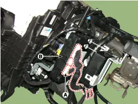
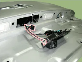
Remove the smart key unit (B) after disconnecting the connectors (A) and loosening bolt and nut.
|
Interior 1 Antenna
Take care not to scratch the crash pad and related parts. |

| 1. |
Disconnect the negative (-) battery terminal. |
| 2. |
Remove the crash pad center panel.
(Refer to Body - "Crash Pad Center Panel") |
| 3. |
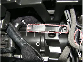
Remove the interior 1 antenna (B) after loosening the mounting nuts (2EA) and disconnecting the connector (A).
|
Interior 2 Antenna
| 1. |
Disconnect the negative (-) battery terminal. |
| 2. |
Remove the console rear complete assembly.
(Refer to Body - "Console Rear Complete Assembly") |
| 3. |
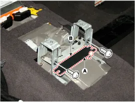
Remove the interior 2 antenna (B) after loosening the mounting screw (2EA) and disconnecting the connector (A).
|
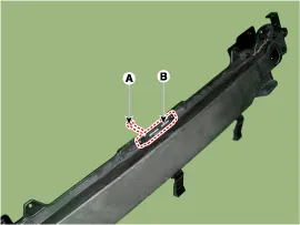
Trunk antenna
| 1. |
Disconnect the negative(-)battery terminal |
| 2. |
Open the rear trunk trim Remove the transverse.
(Refer to Body - "Trunk Trim" ) |
| 3. |
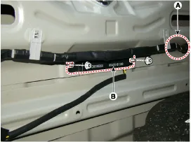
Remove the trunk antenna (B) after disconnect the connector (A) and loosening bolt and nut.
|
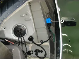
Rear Bumper Antenna
| 1. |
Disconnect the negative (-) battery terminal. |
| 2. |
Remove the rear bumper cover.
(Refer to Body - "Rear Bumper Cover") |
| 3. |
Disconnect the antenna connector (A) on the center of rear bumper. |
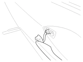
| 4. |
After loosening the nuts (2EA), remove the exterior bumper antenna (B).
|
Buzzer
| 1. |
Disconnect the negative (-) battery terminal. |
| 2. |
Remove the front left wheel guide. |
| 3. |
Disconnect the connectors, then remove the buzzer (A).
|
Door Outside Handle
| 1. |
Disconnect the negative (-) battery terminal. |
| 2. |
Remove the front outside door handle.
(Body - "front door Outside handle")
|
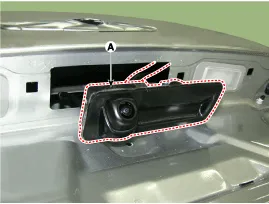
Trunk open switch
| 1. |
Disconnect the negative(-)battery terminal. |
| 2. |
Remove the Trunk lid back panel.
(Body - "trunk lid back panel ) |
| 3. |
Remove the Trunk lid trim.
(Body - "trunk lid trim") |
| 4. |
Remove the trunk open switch assembly (A) after loosening the mounting clip.
|
| 5. |
Disconnect the connector(A), Remove the trunk open switch.
|
| Inspection |
Smart Key Unit
Refer to Smart Key System - "Smart Key Diagnostic"
Smart Key Switch
Refer to Smart Key System - "Smart Key Diagnostic"
Antenna
Refer to Smart Key System - "Smart Key Diagnostic"
Door Outside Handle
| 1. |
Disconnect the front door outside handle connector (A).
|
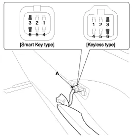
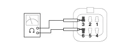
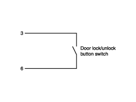
| 2. |
Check for continuity between terminals No 3 and No 6.
|
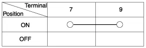
Tailgate Switch
| 1. |
Check for continuity between the tailgate latch terminals.
|
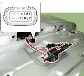
| 2. |
If continuity is not specified, inspect the switch
|
| Installation |
Smart Key Unit
| 1. |
Install the smart key unit. |
| 2. |
Install the smart key unit mounting bolts and connect the connector. |
| 3. |
Install the driver side crash pad lower panel. |
| 4. |
Install the negative (-) battery terminal and check the smart key system. |
Interior 1 Antenna
| 1. |
Install the interior 1 antenna. |
| 2. |
Install the crash pad center panel. |
| 3. |
Install the negative (-) battery terminal and check the smart key system. |
Interior 2 Antenna
| 1. |
Install the interior 2 antenna. |
| 2. |
Install the console rear complete assembly. |
| 3. |
Install the negative (-) battery terminal and check the smart key system. |
Trunk antenna
| 1. |
Trunk mounted antenna. |
| 2. |
Install the Transverse trim. |
| 3. |
Install the negative (-) battery terminal and check the smart key system. |
Rear bumper antenna
| 1. |
Install the rear bumper antenna. |
| 2. |
Install the rear bumper cover. |
| 3. |
Install the negative (-) battery terminal and check the smart key system |
Door Outside Handle
| 1. |
Install the outside handle. |
| 2. |
Install the door trim. |
| 3. |
Install the negative (-) battery terminal and check the smart key system. |
Trunk open switch
| 1. |
Install the trunk open switch. |
| 2. |
Install the rear trunk trim |
| 3. |
Install the trunk lid back Panel |
| 4. |
Install the negative (-) battery terminal and check the smart key system |
Circuit Diagram
Inspection Self Diagnosis With Scan Tool It will be able to diagnose defects of SMART KEY system with GDS quickly. GDS can operates actuator forcefully, input/output value monitoring and self diagnosis.
Categories
- Manuals Home
- Hyundai Genesis Owners Manual
- Hyundai Genesis Service Manual
- Front Door
- Restraint
- Active Air Flap(AAF) Repair procedures
- New on site
- Most important about car

Copyright © 2026 www.hgenesisdh.com - 0.0288