Hyundai Genesis (DH): Smart Key System / Smart Key Diagnostic Repair procedures
Hyundai Genesis (DH) 2013-2016 Service Manual / Body Electrical System / Smart Key System / Smart Key Diagnostic Repair procedures
| Inspection |
Self Diagnosis With Scan Tool
It will be able to diagnose defects of SMART KEY system with
GDS quickly. GDS can operates actuator forcefully, input/output value
monitoring and self diagnosis.
The following three features will be major problem in SMART KEY system.
| 1. |
Problem in SMART KEY unit input. |
| 2. |
Problem in SMART KEY unit. |
| 3. |
Problem in SMART KEY unit output. |
So the following three diagnosis operates will be the major problem solution process.
| 1. |
SMART KEY unit Input problem : switch diagnosis |
| 2. |
SMART KEY unit problem : communication diagnosis |
| 3. |
SMART KEY unit Output problem : antenna and switch output diagnosis |
Switch Diagnosis
| 1. |
Connect the cable of GDS to the data link connector in driver side crash pad lower panel, turn the power on GDS. |
| 2. |
Select the vehicle model and then SMART KEY system.
|
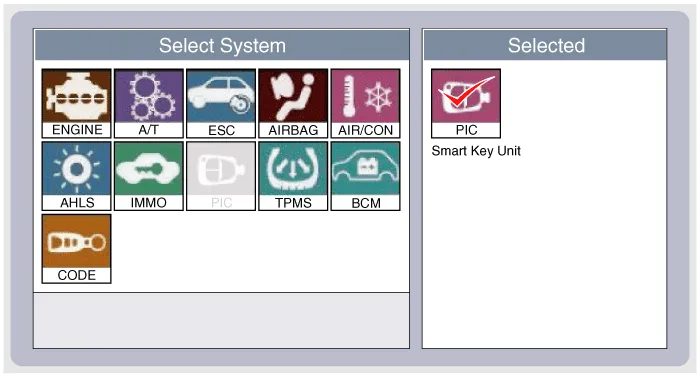
| 3. |
Select the "SMART KEY unit". |
| 4. |
After IG ON, select the "Current data".
|
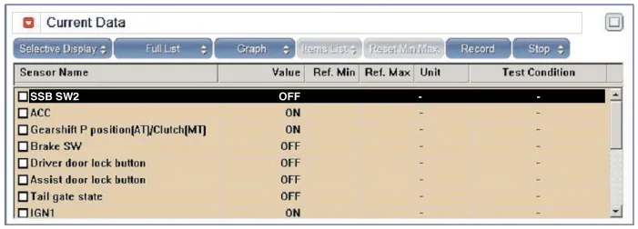
| 5. |
You can see the situation of each switch on scanner after connecting the "current data" process.
|
Communication Diagnosis With GDS (Self Diagnosis)
| 1. |
Communication diagnosis checks that the each linked components operates normal. |
| 2. |
Connect the cable of GDS to the data link connector in driver side crash pad lower panel. |
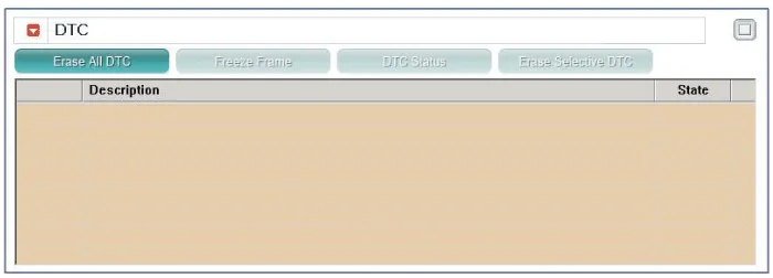
| 3. |
After IG ON, select the "DTC".
|
Antenna Actuation Diagnosis
| 1. |
Connect the cable of GDS to the data link connector in driver side crash pad lower panel. |
| 2. |
After IG ON, select the "ACTUATION TEST".
|
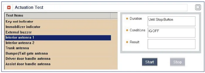
| 3. |
Set the smart key near the related antenna and operate it with a GDS.
|
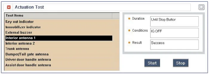
| 4. |
If the LED of smart key is blinking, the smart key is normal. |
| 5. |
If the LED of smart key is not blinking, check the voltage of smart key battery. |
| 6. |
Antenna actuation
|
Antenna Status Check
| 1. |
Connect the cable of GDS to the data link connector in driver side crash pad lower panel. |
| 2. |
Select the "Antenna Status Check".
|
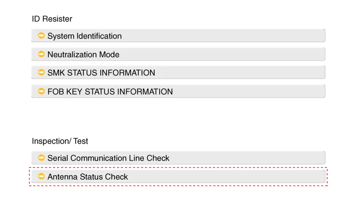
| 3. |
After IG ON, select the "Antenna Status Check".
|

| 4. |
Set the smart key near the related antenna and operate it with a GDS.
|
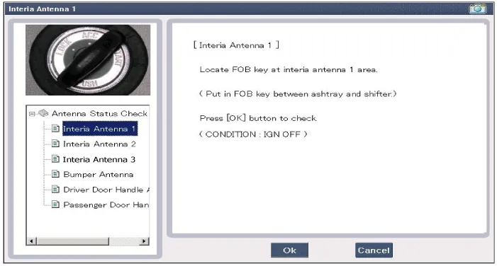
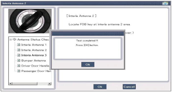
| 5. |
If the smart key runs normal , the related antenna, smart key(transmission, reception) and exterior receiver are normal. |
| 6. |
Antenna status
|
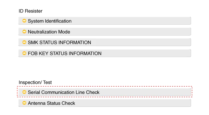
Serial Communication Status Check
| 1. |
Connect the cable of GDS to the data link connector in driver side crash pad lower panel. |
| 2. |
Select the "Serial Communication Line Check".
|
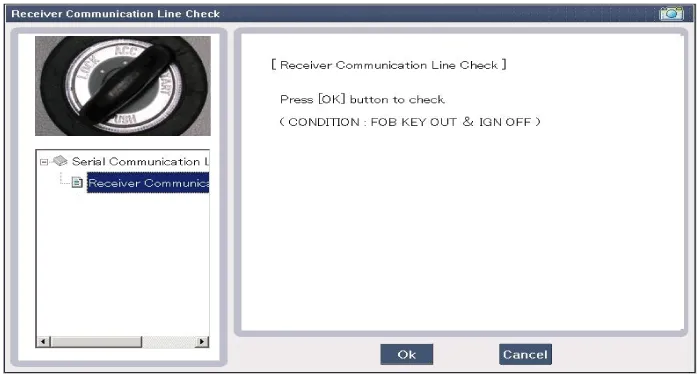
| 3. |
After IG ON, select the "Receiver Communication Line Check".
|
| 4. |
Check the serial communication line with a GDS. |
| 5. |
If the smart key runs normal, the communication of smart key unit and exterior receiver are normal. |
| 6. |
If the smart key runs abnormal, check the following items.
|
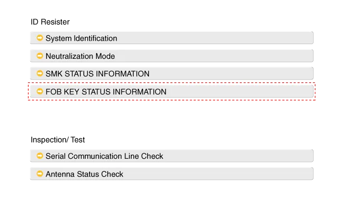
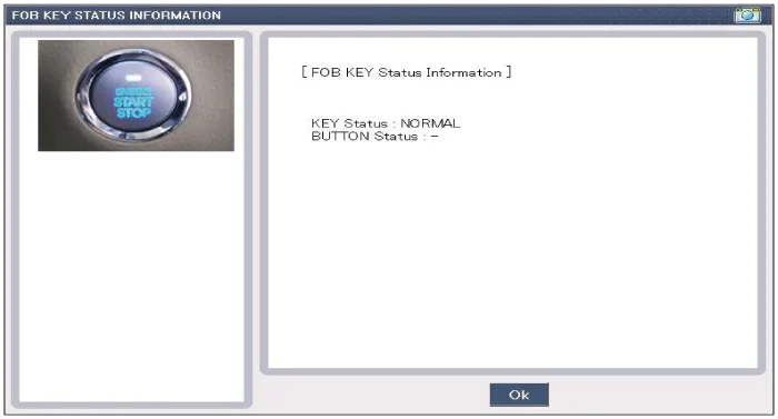
FOB Status Check
| 1. |
Connect the cable of GDS to the data link connector in driver side crash pad lower panel. |
| 2. |
After IG ON, select the "FOB KEY STATUS INFO".
|
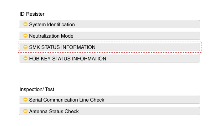
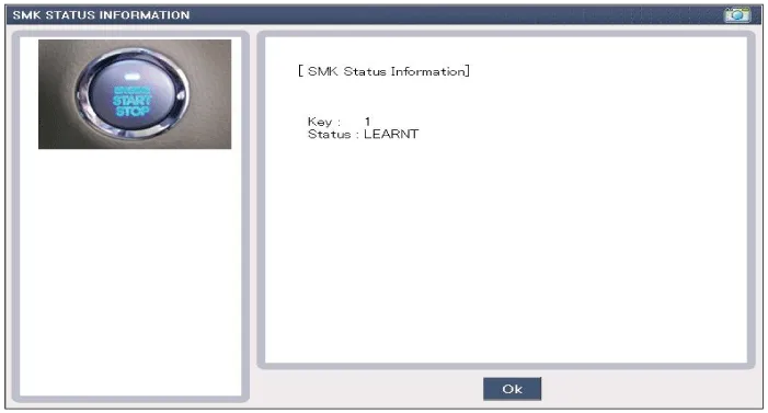
Smart Key Status Check
| 1. |
Connect the cable of GDS to the data link connector in driver side crash pad lower panel. |
| 2. |
After IG ON, select the "SMK STATUS INFO".
|
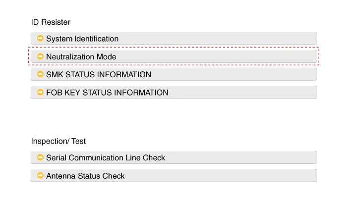
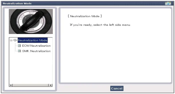
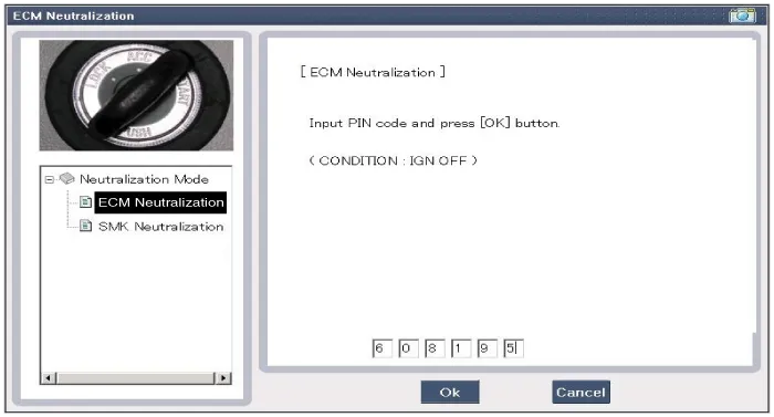
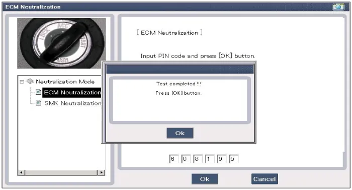
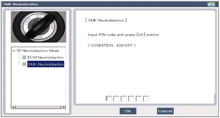
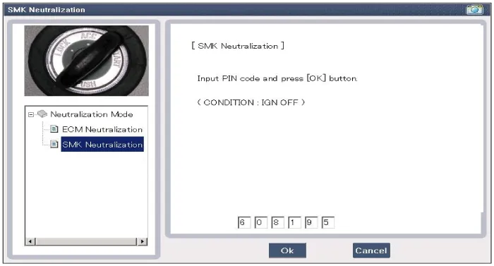
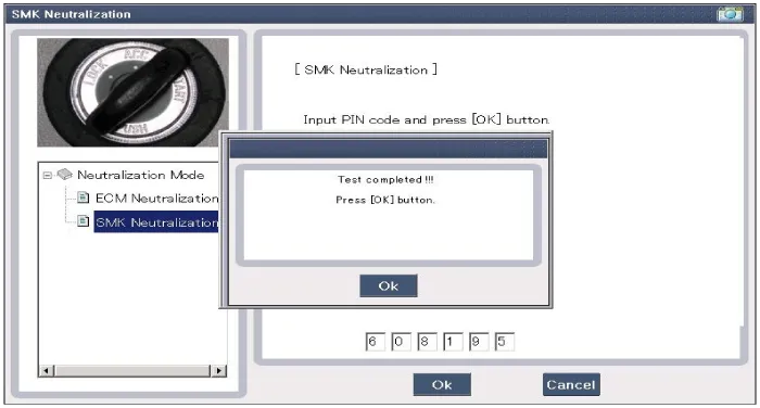
Neutralization Status Check
| 1. |
Connect the cable of GDS to the data link connector in driver side crash pad lower panel. |
| 2. |
After IG ON, select the "Neutralization mode".
|
Removal Smart Key Unit 1. Disconnect the negative (-) battery terminal. 2. Remove the driver crash pad lower panel. (Refer to Body - "Crash Pad Lower Panel") 3.
Other information:
Hyundai Genesis (DH) 2013-2016 Service Manual: Components and Components Location
C
Hyundai Genesis (DH) 2013-2016 Service Manual: Description and Operation
Description System Overview The System offers the following features: - Changing the state of engine ignition and power by using the start button. - Controlling external relays for ACC / IGN1 / IGN2 terminal switching and STARTER, without use of mechanical ignition switch.
Categories
- Manuals Home
- Hyundai Genesis Owners Manual
- Hyundai Genesis Service Manual
- Active Air Flap(AAF) Repair procedures
- Steering System
- Parking Assist Sensor Repair procedures
- New on site
- Most important about car

Copyright © 2026 www.hgenesisdh.com - 0.0436