Hyundai Genesis (DH): ECS(Electronic Control Suspension) System / Schematic Diagrams
| Schematic Diagrams |
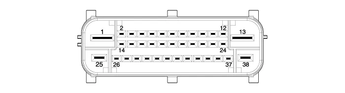
| 1. |
Connector input/output
|
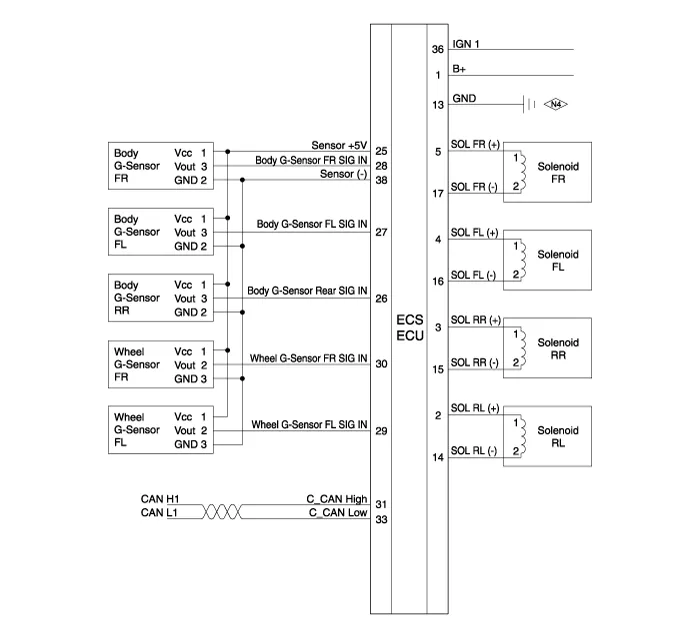
| 2. |
Circuit diagram
|
Description Real-time continuous control of the damping force according to vehicle running conditions and the state of road surface will enhance ride comfort and steering safety, including roll/pitch reduction in case of vehicle dynamics control, quick turning, braking, and starting.
Replacement 1. Disconnect the battery (-) terminal. 2. Remove the trunk luggage side trim [RH]. (Refer to Body - "Trunk Trim") 3. Disconnect the connector and then remove the ECS control unit.
Other information:
Hyundai Genesis (DH) 2013-2016 Service Manual: CO2 Sensor Description and Operation
Description This system maintains the density of carbon dioxide constantly in vehicle interior by measuring the amount of carbon dioxide to increase the comfortableness and the fuel consumption rate when air conditioning system is operating.
Hyundai Genesis (DH) 2013-2016 Service Manual: Climate Control Air Filter Repair procedures
Replacement 1. Remove both stoppers (B) by turning them from the glove box (A). 2. Disconnect the air damper (A) from the glove box (B). 3. Remove the filter cover (A) by pressing the knob. 4. Replace the air filter (A) with a new one according to the direction of air filter.
Categories
- Manuals Home
- Hyundai Genesis Owners Manual
- Hyundai Genesis Service Manual
- Smart Cruise Control Unit Repair procedures
- Body (Interior and Exterior)
- Engine Electrical System
- New on site
- Most important about car
