Hyundai Genesis: ECS(Electronic Control Suspension) System / Description and Operation

Description
Real-time continuous control of the damping force according to vehicle running conditions and the state of road surface will enhance ride comfort and steering safety, including roll/pitch reduction in case of vehicle dynamics control, quick turning, braking, and starting.
Continuously Variable Damper
Damping force variable solenoid valve current will be controlled by ECU. Depending on change in the current amount, , the spool valve will move in the actuator to change flowing route and lead to the damping force variation.
Front Continuously Variable Damper

Rear Continuously Variable Damper

Solenoid Valve

Sensor
Item
Shape
Function
body G-sensor

Body motion detection
Sky hook damping control(pitch, bounce control)
Wheel G-sensor

Wheel roughness detection
Damper velocity estimation
Vehicle Signals
Vehicle Speed
Throttle position sensor
Brake
Steering Angle
Drive mode switch signal
Steering angle sensor

Estimation Of The Driver's Steering
Left/Right acceleration measurements

ECU
Damping force variable solenoid valve current will be controlled by ECU.

Operation
System
Check the MCU and the state of each part when electric power is applied to ECU and prepare to operate. ECU operates the actuator when the engine is started.
System operation mode
Normal operation
4 types of driver selection mode such as “NORMAL” or“ECHO” or “SNOW” and “SPORT” are provided and the mode is changed by linking to the driving integration mode.
Emergency mode
When the failure is detected, the system is converted to the corresponding emergency mode depending on the type of failure and it warning signal blinks.
Damping control
The damping control may improveboth the ride comfort and steering stability. The damping control is implemented through the skyhook control and adoptive style control and The sky hook classifies the body movement into the bounce, roll and pitch and separately controls each one of them. The special driving conditions like the rapid lane changing, abrupt acceleration and abrupt starting restrict the solenoid maximum current to acquire the stability on the vehicle. The solenoid of each wheel is driven with PWM and the target current is output through electric current controlling.
Sky hook control
The vertical movement of the car body is controlled by the vertical acceleration of the body and wheels. The sky hook controls the solenoidal current on each wheel proportionally with the estimated damper speed.
1)
Deciding the road surface
The damping control decides the road surface condition with the vertical acceleration sensor on the front wheel, body and wheels.
The road surface is classified into 5 types of General, Rough road 1, Rough road 2, Wave and Bump through checking the acceleration signal intensity and frequency. The decided road surface according to the pre-determined priority determines the calibration parameter for calculating the target electric current. The road surface decision parameter may be corrected through calibration.
2)
Bounce controlling
The bounce speed of car body can be obtained by adding the vertical speed of 4 wheels. The car body vertical speed can be estimated by integrating the acceleration signal. The required damping force can be calculated by multiplying the proportional gain and bounce speed and through the maximum value limiting function. The calibration parameters are the gain and limit value. The front and rear wheel have different values.
3)
Pitch control
The pitch speed of car body can be obtained through the front/rear wheel car body speed difference. The required damping force can be calculated by multiplying the proportional gain and bounce speed and through the maximum value limiting function. The calibration parameters are the gain and limit value. The front and rear wheel have different values.
4)
Roll control
The car body roll speed can be obtained through the difference on the car body speed. The required damping force can be calculated by multiplying the proportional gain and bounce speed and through the maximum value limiting function. The calibration parameters are the gain and limit value. The front and rear wheel have different values.
5)
Damping speed estimation
The damper speed can be estimated with the difference in the body and wheel vertical speeds, and the vertical speeds of the body and wheel can be obtained through integrating the acceleration sensor signal. The acceleration on rear wheel can be estimated by means of time delay in front wheel and car speed.
6)
Directivity check
The final damping force required by sky hook is decided by “passivity condition.' The passivity checking decides the Y/N of damping force control. The finally required damping force is set through the solenoid electric current control when the required damping force and damper velocity are in the same direction. If they are in the opposite direction, it is set as the soft damping force.
Adaptive control
1)
Anti roll control
The transversal vehicle movement can be estimated by steering angle sensor and car speed. The maximum electric current control is restricted when the transverse jerk movement signal is beyond the set value. The calibration parameters are the jerk signal level controlling the damping force and damping force control amount and they can be set depending on the vehicle speed.
2)
Anti dive control
The speed reducing on the vehicle during braking is calculated by the car speed difference. The maximum electric current control is restricted when the calculated speed reduction is bigger than the set value. The calibration parameters are the speed reduction level and damping force controlling amount.
3)
Anti squat control.
The intention of accelerating by the driver can be expected with the acceleration pedal location information at the start. The maximum electric current control is restricted during acceleration when the location is beyond the set value. The calibration parameters are the speed reduction level and damping force controlling amount.
4)
Vehicle speed sensing control
It is a function to maintain the minimum damping force depending on vehicle speed. The maximum electric current is restricted. The calibration parameter is the damping force controlling amount depending on vehicle speed.
5)
Damping control mode
The driver may choose either of two modes (Auto and Sport). The conversion of the damping modeis linked to the driving integration model. ECS control is performed in AUTO mode when NORMAL mode/ECHO mode/SNOW mode is selected in the driving integration mode switch. ECS control is performed in SPORT mode when SPORT mode is selected. The calibration parameters saved into ECU are changed depending on the selected damping control mode and the vehicle moving performance may differ for each mode. The ride comfort and steering stability are optimized in AUTO mode in general. The SPORT mode focuses on the steering stability.
Components and Components Location
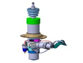
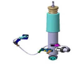
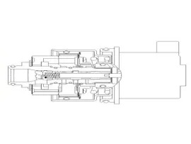
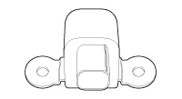
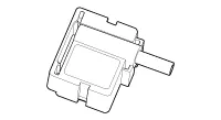
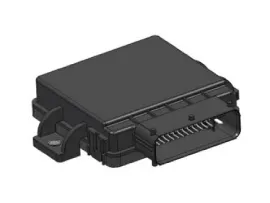
Components 1. ECU2. Front Continuously Variable Damper3. Wheel G-Sensors4. Rear Continuously Variable Damper5. Body G-Sensors Components Location ECS-ECU Body G-Sensors [Right Front] [Le ...

Schematic Diagrams
Schematic Diagrams 1. Connector input/output No.DescriptionPin No.Description1Battery(+)20-2Solenoid RL (+)21-3Solenoid RR (+)22-4Solenoid FL (+)23-5Solenoid FR (+)24-6- 25G- sensor power7- 26B ...

Other information:

Hyundai Genesis (DH) 2013-2016 Service Manual: Tilt & Telescope Control (SCM) Repair procedures


Inspection Ims Mode Setting With GDS 1. You can turn ON/OFF of IMS tilt & telescope control option with the user option program. 2. Select model and "body control module" menu. 3. Select the "Steering Limit Position Setting". 4. Select the "ENABLE". ...

Hyundai Genesis (DH) 2013-2016 Service Manual: Center Pillar Trim Repair procedures


Replacement [Center Pillar Lower Trim]     • Put on gloves to prevent hand injuries.     • When removing with a flat-tip screwdriver or remover, wrap protective tape around the tools to prevent damage to components. • When removing the i ...

© 2013-2024 www.hgenesisdh.com