Hyundai Genesis (DH): Cooling System / Reservoir Tank Repair procedures
Hyundai Genesis (DH) 2013-2016 Service Manual / Engine Mechanical System / Cooling System / Reservoir Tank Repair procedures
| Removal and Installation |
| 1. |
Disconnect the battery "-" terminal from the trunk room. |
| 2. |
Remove the engine cover. |
| 3. |
Remove the engine room cover.
(Refer to Engine And Transaxle Assembly - "Engine Cover") |
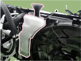
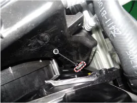
| 4. |
Remove the reservoir tank (A) after loosening the mounting bolts from cooling fan. and then disconnect the over flow hose (B).
|
| 5. |
To install, reverse the removal procedure. |
Removal and Installation 1. Disconnect the battery "-" terminal from the trunk room. 2. Loosen the drain plug and drain the engine coolant. (Refer to Cooling System - "Coolant") 3.
Components 1. Water temperature control assembly2. O-ring3. Water outlet pipe4. Water center pipe5. Water inlet pipe
Other information:
Hyundai Genesis (DH) 2013-2016 Service Manual: PGS Unit (Back & Blinde Unit) Schematic Diagrams
C
Hyundai Genesis (DH) 2013-2016 Service Manual: Auto Defogging Sensor Description and Operation
Description The auto defogging sensor is installed on the front window glass. The sensor judges and sends signal if moisture occurs to blow out wind for defogging. The air conditioner control module receives signal from the sensor and restrains moisture and eliminate defog by controlling the intake actuator, A/C, auto defogging actuator,
Categories
- Manuals Home
- Hyundai Genesis Owners Manual
- Hyundai Genesis Service Manual
- Engine Mechanical System
- Description and Operation
- General Information
- New on site
- Most important about car

Copyright © 2026 www.hgenesisdh.com - 0.032